

Power conversion is very common with today’s electronics. We constantly switch from AC to DC and vice-versa. The common source of AC is the power supply whereas, batteries are used for DC power as and when required. The conversion from AC to DC is, however, an easier way instead of buying a new battery every time you need DC. A rectifier is an electrical device that converts AC signal to DC signal, and is often used in many devices used around us. However, a single stage rectifier does not produce a smooth DC that is usable. Multistage rectification and additional circuitry is required for smoother or usable DC. Let’s look at how that happens.
Half and Full Wave Rectification Basics
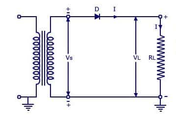
The simplest rectifier is a diode connected to AC power supply. This is also known as a half wave rectifier. A simple half wave rectifier is a single p-n junction diode connected in series to the load resistor. The operation of a half wave rectifier is easy to understand a p-n junction diode conducts current only when it is forward biased.
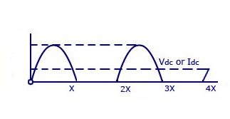
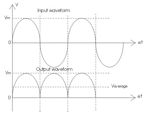
This principle is used in a half wave rectifier to convert AC to DC. The cycle of the input provided here is alternating current. This input voltage is stepped down using a transformer. A p-n junction diode conducts current only when it is forward biased. The same principle is made use of in a half wave rectifier to convert AC to DC. The input here is an alternating current. This input voltage is stepped down using a transformer. Since the diode is forward biased for half cycle of the AC, the output is available only during that half cycle.

To reduce the ripples in the rectifier circuit with capacitor filter:
- RL should be increased.
- input frequency should be decreased.
- input frequency should be increased.
- capacitors with high capacitance should be used.
Full wave rectifier
Like the half wave circuit, a full wave rectifier circuit produces an output voltage or current which is purely DC or has some specified DC component. Full wave rectifiers have some fundamental advantages over their half wave rectifier counterparts. The average DC output voltage is higher than for half wave, the output of the full wave rectifier has lesser ripple than that of the half wave rectifier producing a relatively smoother output waveform.
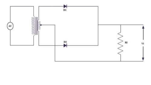
There are two major types of full wave rectifier designs used frequently. The smaller design uses two diodes instead of the single diode used in half wave diode, i.e. one for each half of the cycle. A multiple winding transformer is used where secondary winding is split equally into two halves with a centre tapped connection. The connection for a centre tapped full wave rectifier are shown below.
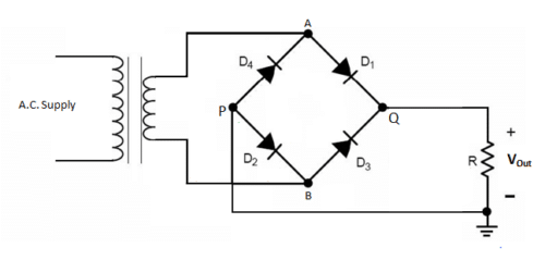
Another configuration requires four diodes connected in an H-bridge configuration. The four diodes labelled D1 to D4 are arranged in “series pairs” with only two diodes conducting current during each half cycle. During the positive half cycle of the supply, diodes D1 and D2 conduct in series while diodes D3 and D4 are reverse biased and the current flows through the load. During the negative half cycle of the supply, diodes D3 and D4 conduct in series, but diodes D1 and D2 switch “OFF” as they are now reverse biased. The current flowing through the load is the same direction as before.
Filtering the rectified voltage
The output across the diodes in the above steps is neither complete nor is it completely DC. The output is not steady DC and is not practical to use with circuits. A filter circuit also known as a smoothing capacitor is added to the rectifier circuit to improve the output. Smoothing capacitors are connected in parallel with the load across the output of the full wave bridge rectifier. This filter circuit increases the average DC output level as the capacitor acts like a storage device. The smoothing capacitor converts the rippled output of the rectifier into a smoother DC output.
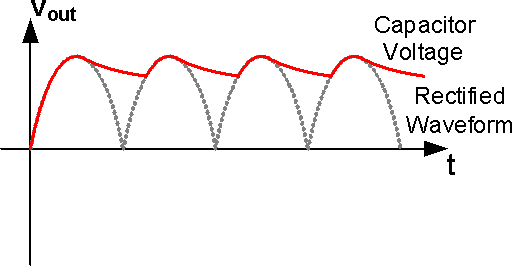
However, there is still a minor ripple in the output can be smoothened out by the varying the capacitor values. The ripple voltage is inversely proportional to the value of the smoothing capacitor. These two are related by the following formula:
Vripple = Iload/(fxC)
An alternative is to use a voltage regulator IC for a constant DC power supply.
What is Form Factor?
The form factor is the ratio of RMS value to the DC value.
The form factor of a half-wave rectifier is equal to 1.57 and for full-wave rectifier is 1.11.
You can check out constructing of a Full Bridge rectifier here with a video tutorial:


Awesome
Thank You for your feedback.
Fantastic
When use an transformer with center tapped connection and full bridge rectifier may obtain +V, and – V from GND ( the center tapped connection), it is an interesting connection to be mentioned…