

In the third topology, constant power output fly-back converter is used. The DC to DC converter is designed to produce an open circuit output voltage of 10-15kV and a power output delivery rating equal to product of a little more than the required magnitude of DC voltage and desired discharge current. As a consequence, the converter output voltage rapidly drops to the desired value after the discharge is initiated.
Diode-capacitor multiplier chain
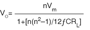
There are two common voltage multiplier configurations, one for the odd multiplication factors (Fig. 4) and the other for even multiplication factors (Fig. 5). The output voltage in case of multiplier configuration shown in Fig. 4 is given by:

In the case of multiplier chain with even multiplication factor, the output voltage is given by:
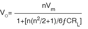
In both cases, C1=C2=C3=C4=C5=C6= C7=C8=C, n is the multiplication factor, f is frequency of operation equal to power-line frequency for AC-DC power supply and the switching frequency in case of a switched mode power supply. VP is the peak amplitude of the voltage applied to the input of multiplier chain. Also, in both cases, multiplied output voltage is equal to nVP, provided the bracketed term in the denominator is zero or negligible. This is possible for large value of capacitance C.
Another voltage multiplier circuit that offers a superior performance is the one that uses unequal capacitors. Fig. 6 shows the circuit configuration.
Helium-neon power supply circuits
The most commonly used helium-neon laser power supply circuit is a push-pull type high-frequency switched mode DC-to-AC power supply cascaded to a diode-capacitor type voltage multiplier chain, as shown in Fig. 7. The push-pull circuit generates a high-frequency square waveform across transformer secondary, which is then multiplied to generate the starting high voltage for the discharge tube. The push-pull circuit here is configured around a switching control IC type LM3524.
It may be mentioned here that, a large number of control ICs intended for switching power supply design are commercially available. Some of the other popular type numbers include TL497, TL594 and TDA8130. Their data sheets contain typical application circuits for switching supply design.
When discharge occurs, the voltage falls to a lower value to supply the sustaining discharge current through the ballast resistance. The rest of the voltage is dropped across the multiplier chain components. In some cases, the sustaining voltage may be tapped from an earlier point in the chain for better overall performance. In that case, the output of the multiplier chain feeds the discharge tube through a relatively high resistance of the order of tens of mega-ohms and the sustaining voltage feeds the tube through the ballast resistance.
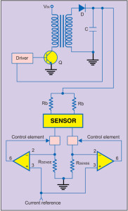
The other common circuit topology is the one where the power supply generates the voltage required to sustain the discharge and a high-voltage trigger circuit generates the starting voltage to initiate the discharge. Fig. 8 shows a typical circuit. The power supply is configured around an externally driven fly-back type DC-to-DC converter. The ballast resistance is split into two resistances.
Initially, when there is no discharge, the voltage appearing after RSENSE is equal to open circuit voltage. A fraction of this voltage is compared with VREF and the comparator drives the high-voltage trigger circuit configured around SCR, R-C components and trigger transformer. As soon as discharge is struck, voltage appearing after RSENSE drops and the drive pulses are withdrawn from SCR gate. The power supply provides the discharge current through series connection of resistors constituting ballast resistance.
In the third circuit topology, the converter circuit is designed to deliver an output power equal to the product of the required sustaining voltage at the power supply output and the discharge current. Since it is a constant-output-power converter, the output voltage would increase without limit in the ideal case in the event of zero current drawn from the power supply. When the output voltage exceeds the required initiating voltage, the plasma current drawn from the power supply forces the output voltage to fall to the sustaining voltage governed by the output power capability of the converter.
Compact helium-neon laser power supplies are commercially available both as AC-operated bench-top versions as well as DC-operated supplies for OEM market (Fig. 10). Helium-neon lasers with an integrated power supply are also available (Fig. 11).
Power supplies for ring laser gyroscope sensors
A ring laser gyroscope comprises a helium-neon ring laser cavity with two counter-propagating laser beams. A ring laser gyroscope, which is the heart of the inertial navigation systems of modern aircraft, missiles etc, makes use of a ring helium-neon laser in a closed cavity. Without going into details of its operational principle, it would suffice to mention here that stability of discharge current in each arm of the ring laser cavity is very crucial for proper functioning of the device. Also, it is important to have a stable value of difference between the currents in the two arms.


