

This article discusses the criteria for selecting the right microcontroller (MCU) for different embedded applications. It also discusses the design challenges and system limitations of MCUs in embedded applications.
Microcontroller application in home appliance industry
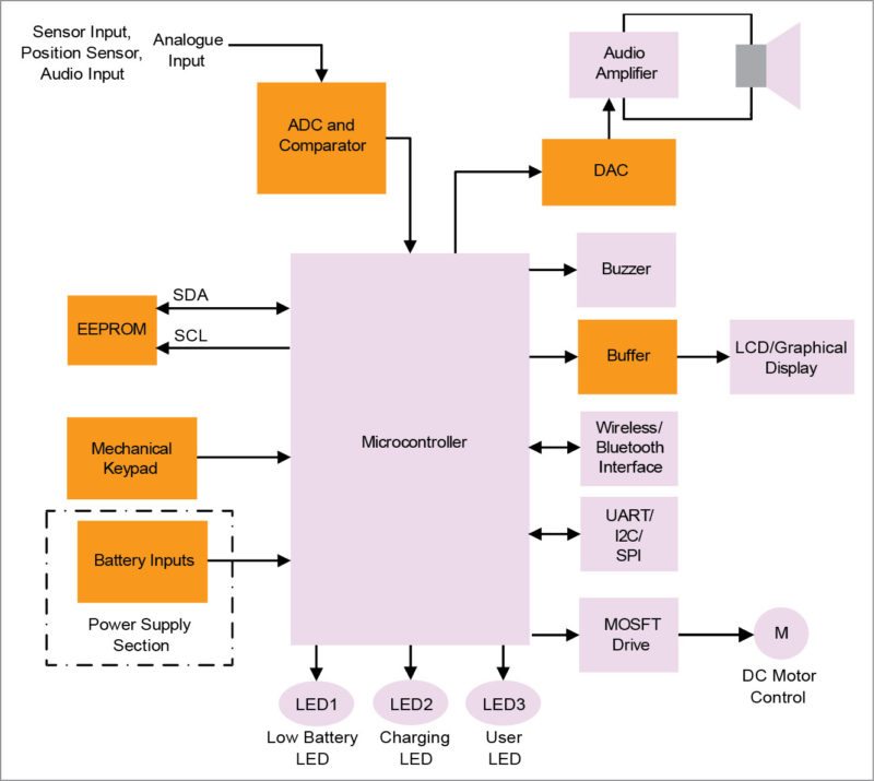
The home appliance industry uses 8/16/32-bit microcontroller based circuitry for motor control and TRIAC/LED/LCD drive applications. A microcontroller controls and manages all functions and features of the home appliances. When you press Start button, inputs go to the MCU from the front-panel keyboard and the MCU starts the three-phase brushless DC (BLDC) motor or the permanent magnet synchronous (PMSM) motor. Motor speed is varied and controlled as per your input from the front-panel keypad.
Also Read: Difference Between Microcontroller and Microprocessor

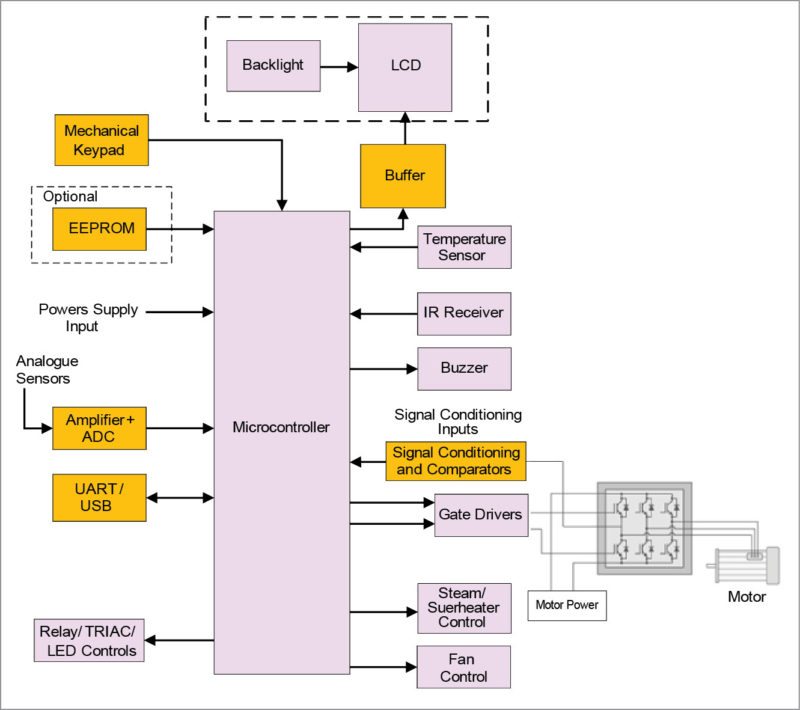
The MCU uses either internal or external serial EEPROM (I2C/SPI based) to store old data. It uses a real-time clock for displaying accurate time. Temperature measurement is done using an onboard resistance temperature detector, thermistor or thermocouple based temperature-sensing device.
The MCU uses an external analogue-to-digital converter (ADC) and amplifiers for different analogue inputs from sensors, temperature sensors and battery. It uses external signal conditioning, comparators and gate-driver circuitry for driving and controlling the three-phase BLDC/PMSM motor. The MCU receives remote control inputs through an infrared receiver (at 38kHz input).
The MCU uses external buffer-driver circuitry to drive 7-segment LED/LCD/graphical display. Typically, a 7-segment LED/LCD/graphical display with backlight is used for showing the temperature, battery voltage, speed and error/warning messages. The MCU also interfaces with onboard peripherals like I2C/SPI and external peripherals like UART/USB for communication.
Microcontroller in automotive industry
The current automotive industry uses 16- to 32-bit microcontroller based circuitry for e-bikes. The circuitry controls and manages all functions and features of the automobiles. Once you use the ignition key to start the automobile, inputs go to the MCU. This starts the three-phase brush-less automotive motor. The MCU receives vehicle input signal and the vehicle starts moving. The MCU uses driver circuitry to drive the three-phase brush-less automotive motor as per speed required by the user. Speed of the motor varies and is controlled as per acceleration brake sensor input from the user.
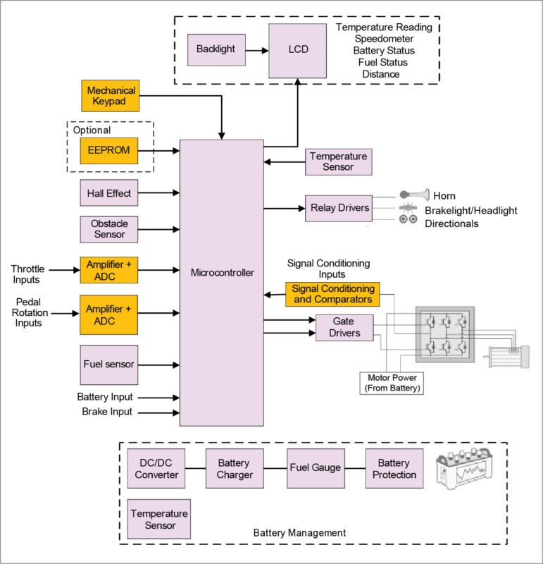
The MCU uses either internal or external serial EEPROM (I2C/SPI based) for storing data like distance readings. It uses RTC for displaying accurate time on the display. Temperature measurement is done by using an onboard RTD or thermistor based temperature-sensing device.
The e-bike solution in the automotive industry uses an obstacle sensor to get information about nearby vehicles while parking, a fuel sensor to get information regarding the amount of fuel in the tank, while an MCU monitors battery voltage and shows it on the LCD display. The MCU uses relay-driver circuitry for switching brakelight/headlight on or off and for blinking directional lights.
The power supply section uses rechargeable lead-acid/lithium battery as the power source. It also has provision for a battery charger. Battery input is down-converted to DC voltage to power the MCU and other circuitry. Ignition key of the e-bike enables and disables onboard regulators.
The power supply section incorporates protection features for battery, over-current, over-heating and start-up fail, which are controlled by the MCU. It also enables charging of external devices like mobile phones.
Microcontroller application in mobile phones and tablets
Current mobile phone and tablet designs use 8/16/32-bit MCUs as a co-processor for different functions. The MCU receives signals from analogue sensors (temperature sensors like thermistors, resistance temperature detectors and humidity sensors that receive analogue inputs and provide digital voltage, which is applied to the MCU), 2/3-axis accelerometers (that measure 2/3-axis movements and convert it to digital voltage, which is applied to the MCU) and ambient light sensors (ALSes) interface.
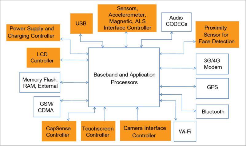
Ambient light sensor enables automatic control of display backlight brightness over a wide range of illumination conditions, from a dark environment to direct sunlight. With ALS input, an MCU or baseband processor increases or decreases display brightness, depending on the environment. The MCU also receives magnetic sensor inputs through external ADCs and buffer circuitry. Besides, it uses the accelerometer and mechanical joystick for running gaming applications.
The microcontroller uses proximity sensors for face detection and hand-movement (grip detection) in mobile phones. When you move the phone near your face, the MCU switches off the keypad, and when you move your hand near the keypad, it activates/switches on the keypad. The MCU uses host interrupt feature to activate broadband and application processor for face detection.
The MCU enables face detection by detecting proximity of your face, ear or head to eliminate false touches of the touchscreen. This reduces talktime power by powering down the touchscreen. It is implemented by using infrared proximity sensors.
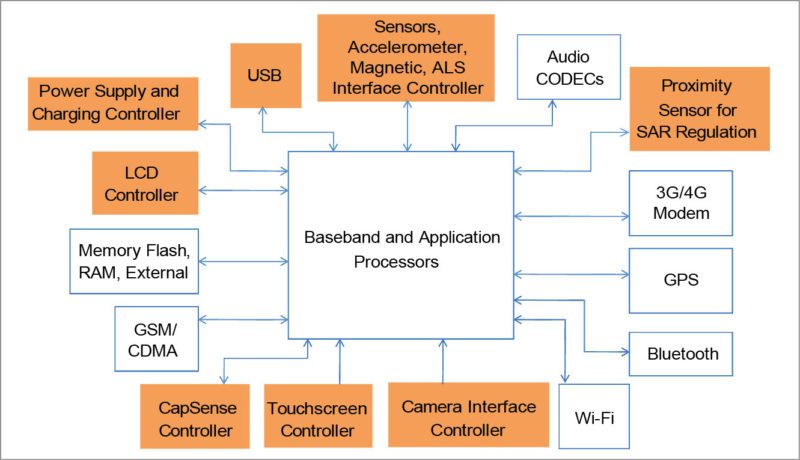
The MCU uses a proximity sensor for specific absorption rate (SAR) regulation in tablet applications. SAR is the rate at which energy is absorbed by the human body when exposed to radio-frequency electromagnetic waves. The proximity sensor dynamically regulates radio transmissions near human beings.
The MCU uses external buffer-driver circuitry to drive LCD or graphical displays. Typically, an LCD or a graphical display with backlight is used in low-end mobile phone applications. The MCU also controls the backlight of LCD and graphical displays. It uses touchscreen controllers for the touchscreen interface in high-end mobile phone applications.
The MCU uses a mechanical keypad for your inputs in low-end mobile phone applications. It uses CapSense/touchscreen based keypads in high-end mobile phone applications.
The MCU monitors lithium-ion battery voltage and is also used for battery-charging application. It is also used for fault detection and data recovery in mobile phones.
The microcontroller uses haptics (tactile feedback technology) in mobile phones for replacing mechanical buttons that interface with you through the sense of touch by applying force, vibration or motion.
The MCU interfaces with broadband and application processor and other onboard peripherals (like camera interface controller) through I2C and SPI interfaces. It interfaces with broadband and application processor in host (master) and slave mode for data transfer. Broadband and application processor use onboard USB 2.0/3.0 controller to transfer data externally.
Microcontroller application in electronic toys
Current electronic toys use 8/16-bit MCUs for motor control, LED/LCD/graphical display drives, different input and output interfaces, battery sensing and audio output. An MCU in chip-scale package (CSP) is most commonly used in electronic toys.
The MCU receives signals from analogue sensors (that receive analogue input and provide digital voltage, which is applied to the MCU) and 2/3-axis accelerometer (that measure 2/3-axis movement and convert it to digital voltage, which is applied to the MCU). It also uses the accelerometer and mechanical joystick for running gaming applications.
The MCU uses external buffer-driver circuitry to drive LED, LCD or graphical displays. Typically, LCD or graphical displays with backlight are used in low-end applications. The MCU also controls the backlight of LCD and graphical displays. It uses a touchscreen controller for the touchscreen interface in high-end applications.
The MCU uses a mechanical keypad for inputs in low-end applications. It uses CapSense/touchscreen based keypads in high-end applications. The MCU interfaces with other onboard peripherals (like camera interface controller) through I2C, SPI and UART interfaces.
Toy applications use coin-cell or lithium-ion batteries for operation. The MCU monitors the coin-cell or lithium-ion battery voltage, and even battery-charging. It is also used for fault-detection and data-recovery applications.
The MCU used in proprietary 2.4GHz technology is targeted for remote-controlled toy. Gaming controllers and remote-controlled toys are also witnessing customers shifting from infrared to radio frequency.
System limitations and use of PSoC
A programmable system on chip (PSoC) is a combination of an MCU with programmable logic and high-performance analogue-to-digital converters and commonly-used fixed-function peripherals. The PSoC family is made up of 8-bit (PSoC1 and PSoC3) and 32-bit MCUs (PSoC4 and PSoC5). These have flash memories up to 256kB, SRAM up to 64kB and internal EEPROM up to 2kB. (Flash can be used to emulate EEPROM.) PSoC works in ultra-low power mode. In this mode, it consumes less than 1µA current, which is useful for operating in standby mode.
Using PSoC Creator IDE tool, all interface and logic can be designed. This tool is a readily-available component block for designing interface and logic like SARADC and PGA for analogue sensors and other inputs. PWM, CLK, MUX and comparator components are used for motor-drive applications. Character LCD and segment LCD components directly (do not require external buffers) drive LCD/graphical LCDs.
The tool also has a real-time clock component for real-time measurement. It has an internal system clock and so does not require external clock/oscillator circuitry. Its other components include a timer, buzzer, infrared and fan controller.
PSoC Creator IDE tool enables you to make use of an entire tools ecosystem with integrated compiler tool chains, RTOS solutions and production programmers. With this tool, you can create and share user-defined custom peripherals using hierarchical schematic designs. You can automatically place and route chosen components and integrate simple glue logic, normally located in discrete devices.
A PSoC supports CapSense technology, which replaces mechanical buttons with a CapSense based keypad. This reduces failure due to mechanical buttons and provides better product reliability. PSoC Creator IDE tool supports CapSense SmartSense component, which auto-tunes the sensitivity of CapSense buttons and slider (does not require manual tuning).
A PSoC supports the waterproofing application. It also supports proximity function for the front keypad; the front keypad gets activated when you place your hand near the keypad.
A PSoC can directly drive LED and LCD displays (segment LCDs, graphic LCDs and character LCD displays) for displaying channel and volume information. It has an operating range of 1.71V to 5.5V, so it can be easily interfaced with external peripherals for other applications.
A PSoC works in ultra-low power mode. In this mode it consumes less than 1µA current, which is useful for low-power-battery based applications.
A PSoC has internal PGA, comparators and configurable delta-sigma ADC with 8- to 20-bit resolution, with sample rates up to 192ksps. It is used to measure different analogue and battery inputs.
Implementation of touchscreen based design on the front panel instead of an LCD display and keypad provides better user interface and flexibility.
External devices. PSoC can communicate with external devices like iPod and iPhone through UART and USB protocol. You can control such devices.
PSoC4 supports code security for home appliance solutions due to programmable architecture. A PSoC can connect to devices like Bluetooth controllers, so that you can create a network of automated devices.
In the world of cortex processors, operating range is up to 3.3V. PSoC4 supports an operating range of 1.71V to 5.5V.
Failure analysis and returned materials
Increasing the number of internal and external interfaces on the board will increase the number of ways that an intruder can create havoc on the system. This is one of the single-largest limitations of this embedded system, which can be solved by a single-chip solution.
A PSoC has an internal RTC component for real-time measurement. It does not require external clock/oscillator circuitry.
It supports USB 2.0 interface, allowing you to interface external memory (hard disk) through USB 2.0. It also supports SD card interface. A PSoC has an internal 8-bit digital-to-analogue converter (DAC), which can be used for controlling speaker volume and for muting the speaker.
Design challenges
An MCU with one-time programmable feature prevents reverse engineering of the firmware by competitors and hackers. Implementing protection against voltage fluctuations, waterproofing and water-tolerance is a design challenge for the system designer. The solution involves electromechanical construction and designing a compact and cost-effective electromechanical solution.
Certifying this electromechanical design with EMI/EMC standards is another challenge for the designer. Using flexible printed circuits interface for displays, touch panels and buttons is also a design challenge.
A PSoC supports CapSense technology. Using PSoC in the design, CapSense based button, slider and proximity can be implemented for front-panel design. Meeting CapSense performance (signal-to-noise ratio) with nearby LEDs (PWM based) on the front panel is also a challenge for the system designer.
Implementing auto-tuning with variation in trace capacitance, variation in CapSense button and slider sizes and shape are other design challenges, along with implementing CapSense sensing with thicker glass material (display glass) and meeting CapSense sensitivity with that type of materials.
Fault detection and recovery mechanism is required in most application. Power supply design with battery protection, over-current, over-heating, start-up fail condition is required for home appliance applications. Implementing self-diagnostics in home appliance applications is another design challenge for the system designer.
Last, but not the least, as final solution is expected to work 24/7 continuously, component selection and reliability is a challenge.
Conclusion
A PSoC is a combination of an MCU and ASIC. It provides ease-of-use environment. Using PSoC in above-discussed applications helps reduce product cost (by reducing bills of materials cost) and project cost (with PSoC Creator and PSoC Designer implementation).
Ronak Desai is system engineering manager at Cypress Semiconductor, Bengaluru


