 Almost all restaurants have handwash sinks for the use of their customers. Since it is used by numerous people, the tap stops working properly after some time and starts leaking, leading to a waste of water. This Motion Activated Tap Water Flow Circuit can prevent the problem as it lets the water flow from the tap automatically only when a person comes in front of the sink.
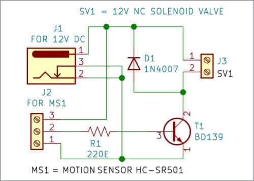
The circuit is built around a DC barrel jack (J1), PIR sensor HC-SR501 (MS1), transistor BD139 (T1), a normally-closed solenoid valve (SV1), and a few other components. The circuit can be powered by a 12V battery or an external 12V DC adaptor.

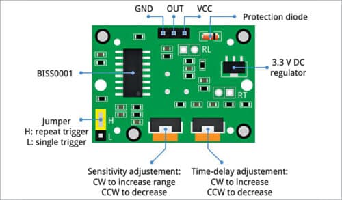
Before understanding the working of the project, let us understand the workings of the PIR motion sensor, which is the heart of this circuit. Fig. 2 shows the front side of the PIR motion sensor while Fig. 3 shows its backside.

HC-SR501 is a low-cost passive infrared sensor used to detect any kind of motion. It has a wide operating voltage of 4.5V to 20V and two operating modes—repeatable mode and non-repeatable mode.
In repeatable mode (H: repeat trigger in Fig. 3), the sensor output goes high when motion is detected. It stays high as long as the person is in the range of the sensor. When the person moves out of its range, its output goes low—after a pre-set time.
In non-repeatable mode (L: single trigger in Fig. 3), the sensor output goes high only for the pre-set time when motion is detected. Any movement during this period does not affect the output, so water keeps flowing during this period. It triggers only once and is not re-triggered. In this project, we have used the repeatable mode.
On the back side of the sensor, there is a jumper and two variable resistors, as shown in Fig. 3. The jumper is used to select the operating mode. One variable resistor is used to vary the sensitivity of the sensor and the other to vary its time delay.
The working of the circuit is simple. Normally, the sensor output is low, and the valve is not energized. When a person comes in front of the PIR motion sensor, the sensor’s output becomes high as long as the person is within the range and energizes the solenoid coil. The valve opens and water starts flowing from the tap.
| Parts List |
| Semiconductors: D1 – 1N4007 rectifier diode T1 – BD139 NPN transistor Resistors (all 1/4-watt, ±5% carbon): R1 – 220-ohm Miscellaneous: J1 – DC barrel jack J2 – 3-pin terminal connector J3 – 2-pin terminal MS1 – HC-SR501 PIR motion sensor SV1 – 12V NC solenoid valve, Single-changeover relay |
When the sensor detects no one within its range, its output becomes low, and the solenoid coil gets de-energized. Thus, water flows from the tap only when someone is within its range and stops automatically when a person moves away.
Construction and testing
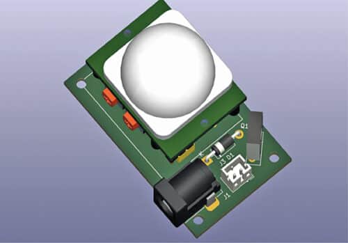
Being quite simple, the circuit can be assembled on a general-purpose PCB. After assembling the circuit, enclose it in a suitable box. Install the motion sensor in front of the handwash sink in such a way that when someone comes in front of it, the tap water starts flowing.
In non-repeatable mode (L: single trigger in Fig. 3), the time for water flow can be pre-set through the time-delay adjustment pot (on the right-hand side in Fig. 3). Sensitivity can be set by sensitivity-adjustment pot (on the left-hand side in Fig. 3).

EFY Notes.
- Fix the solenoid valve in the proper water flow direction. The direction is marked in the valve housing.
- There is a minimum pressure required for the proper functioning of the valve. The water storage tank should be at a height of at least three meters above the valve, otherwise, the use of a water pressure pump would be required.
Related Projects
- Automatic Water Pump Controller
- Automatic Water Pump Motor Controller
- Automatic Water level controller
A. Samiuddhin, a circuit designer, is B.Tech in electrical and electronics engineering. His interests include LED lighting, power electronics, microcontrollers, and Arduino programming


