An infra-red or wireless remote control has the disadvantage that the small, handy, remote (transmitter) is often misplaced. The sound operated switch has the advantage that the transmitter is always with you. This project offers a way to control up to four latching switches with two claps of your hand. These switches may be used to control lights or fans—or anything else that does not produce too loud a sound.

To prevent an occasional loud sound from causing malfunction, the circuit is normally quiescent. The first clap takes it out of standby state and starts a scan of eight panel-mounted LEDs. Each of the four switches are accompanied with two LEDs—one for indicating the ‘on’ and the other for indicating the ‘off’ state. A second clap, while the appropriate LED is lit,activates that function. For example, if you clap while LED10 used in conjunction with Lamp 1 is lit then the lamp turns on. (If it is already on, nothing happens and it remains on.
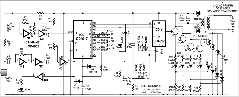
A condenser microphone, as used in tape recorders, is used here to pick up the sound of the claps. The signal is then amplified and shaped into a pulse by three inverters (N1 through N3) contained in CMOS hex inverter IC CD4069. A clock generator built from two of the inverter gates (N5 and N6) supplies clock pulses to a decade counter CD4017 (IC2). Eight outputs of this IC drive LEDs (1 through 8). These outputs also go to the J and K inputs of four flip-flops inside two CD4027 ICs (IC3 and IC4). The clock inputs of these flip-flops are connected to the pulse shaped sound signal (available at the output of gate N3).
Additional circuitry around the CD4017 counter ensures that it is in the reset state, after reaching count 9, and that the reset is removed when a sound signal is received. Outputs of the four flip-flops are buffered by transistors and fed via LEDs to the gates of four triacs. These triacs switch the mains supply to four loads, usually lamps. If small lamps are to be controlled, these may be directly driven by the transistors.
If this circuit is to be active, i.e.scanning all the time, some components around CD4017 IC could be omitted and some connections changed. But then it would no longer be immune to an occasional, spurious loud sound.
The condenser microphone usually available in the market has two terminals. It has to be supplied with power for it to function. Any interference on this supply line will be passed on to the output. So the supply for the microphone is smoothed by resistor-capacitor combination of R2, C1 and fed to it via resistor R1.
CD4069, a hex unbuffered inverter, contains six similar inverters. When the output and input of such an inverter is bridged by a resistor, it functions as an inverting amplifier. Capacitor C2 couples the signal developed by the microphone to N1 inverter in this IC, which is configured as an amplifier. The output of gate N1 is directly connected to the input of next gate N2. Capacitor C3 couples the output of this inverter to N3 inverter, which is connected as an adjustable level comparator. Inverter N4 is connected as an LED (9) driver to help in setting the sensitivity.
Preset VR1 supplies a variable bias to N3. If the wiper of VR1 is set towards the negative supply end, the circuit becomes relatively insensitive (i.e. requires a thunderous clap to operate). As the wiper is turned towards resistor R4, the circuit becomes progressively more sensitive. The sound signal supplied by gate N2 is added to the voltage set by preset VR1 and applied to the input of gate N3. When this voltage crosses half the supply voltage, the output of gate N3B goes low.
The output of gate N3 is used for two things: First, it releases the reset state of IC2 via diode D1. Second, it feeds the clock inputs to the four flip-flops contained in IC3 and IC4. In the quiescent state, IC2 is reset and its ‘Q0’ output is high. Capacitor C4 is charged positively and it holds this charge due to the connection from R5 to this output (Q0).
IC2 is reset and its ‘Q0’ output is high. Capacitor C4 is charged positively and it holds this charge due to the connection from R5 to this output (Q0). IC2 is a decade counter with fully decoded outputs. It has ten outputs labelled Q0 to Q9 which go successively high, one at a time, when the clock input is fed with pulses. IC3 and IC4 are dual JK flip-flops. In this circuit they store (latch) the state of the four switches and control the output through transistors and triacs.


