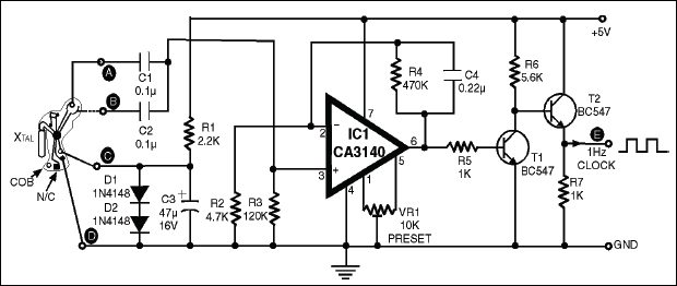
 Usually the circuits for generation of 1Hz clock for applications in digital clock and counter circuits make use of ICs in conjunction with a crystal and trimmer capacitors, etc. However, similar or better accuracy can be achieved using a chip-on-board (COB) device found inside a digital clock, which is readily available in the market for Rs 15-20. This COB consists of IC, capacitors and quartz crystal, etc which are mounted on its surface. It works on 1.4 volt DC source. This COB can be used to derive 1Hz clock.

Resistor R1, capacitor C3, diodes D1 and D2 shown in the circuit convert 5V DC into 1.4V DC. A ½Hz clock is available at terminals A and B with a phase difference of 90o. The two outputs, are combined using capacitors C1 and C2 to obtain a complete 1Hz clock. This 1Hz clock pulse has a very low amplitude of the order of a few milli-volts which cannot be used to drive the digital circuits directly. This low-level voltage is amplified several times by op-amp IC CA3140.
 The op-amp CA3140 is connected in a non-inverting mode, and its gain is set by resistors R4 and R3. Capacitor C2 reduces the AC gain and unwanted stray pick-up and thus improves stability of the circuit. The input impedance of IC CA3140 is very high and thus there is no drop at the input when 1Hz clock signal of low level is connected across its input terminals from the COB. Amplified 1Hz clock pulse is available at its output pin 6, which is further amplified by transistors T1 and T2 to drive the digital clocks and timers.
Preset VR1 is offset null control used to adjust proper 1Hz pulse at the output terminal ‘E’. Connect one LED in series with 220-ohm resistor between the terminal ‘E’ and ground and adjust preset VR1 till the LED blinks once every second. When using the COB, affix the same on a general-purpose PCB using rubber based adhesive and solder the terminals neatly using thin single-strand wire.
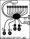
Lab Note: The COBs used in different watches may differ some what in their configuration. But by trial-and error one can always find out the appropriate points corresponding to points A, B, C and D. Figure of a second COB used by EFY Lab is shown alongside. The points A and B (on the COB used by us) were observed to have complementary 1Hz outputs and hence anyone (only) could be used as input to opamp CA3140.


