Looking for a graphical interface to design neuronal models and neural networks? ‘iqr’ is the perfect free solution for you. This article gives you an idea of how to start working with it
Neural networks are one of the artificial intelligence techniques that allow you to create ‘smart’ systems. These networks have also recently created a new frontier in power electronics and other segments within electronics.
iqr, which we will discuss in this article, is a simulation tool for large-scale neural networks. It introduces students to neuronal simulation and neuromorphic control. If you are looking for a graphical interface to design neuronal models, iqr is the perfect free solution. Not only does it provide a graphical interface but also graphical online control of the simulation.

Some of its important features are that we can change the model parameters at run time, and that it has predefined interfaces for robots, cameras and other hardware. It also presents a multi-level neuronal simulation environment to the user. Its modular architecture is open, enabling easy writing of new neurons, synapses and interfaces to new hardware.
Currently, there are alternative simulation tools available that you might already be familiar with, like MATLAB, for instance. However, iqr delivers an advantage over high-level general-purpose simulation tools like MATLAB, since it has predefined building blocks that allow the easy and fast creation of complex systems.
Also Read: Neural Network Optimization
Also, iqr’s approach differs from highly-specific low-level simulation software like Neuron, which focuses more on the thoroughness of the model than its size and the speed of simulation. iqr, on the other hand, is more concerned about connectivity between the neuronal models than their details, and also with their ability to interact with the real world.

System Requirements
OS: Windows, Mac OS, Linux
HDD space: 34.9 MB
Working with iqr
1. Starting up iqr: To start, double-click on the IQR icon on the desktop.
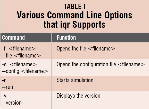
The various command line options that iqr supports are listed in Table I.
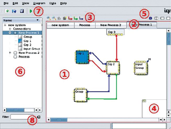
2. The user interface: The diagram editing panel(1) adds processes, groups and connections to the model. A single process or group is selected by clicking on its icon. To select multiple processes or groups, press the Control key and select.
Defining a new process will add a new tab(2) and a new diagram. This Tab bar can be used to switch between processes. The leftmost Tab presents the system level.

The diagram editing toolbar(3) consists of functions like zooming in/out, adding a new process, a new group, and new connection buttons.
Pannel(4) is to navigate through the large diagrams and change the visible section of the diagrams.
Splitter(5) splits the diagram into separate views. From left to right: you can split vertically, horizontally, or revert to a single window view.
Browser(6) gives the option to directly access the elements of the system. The top node is for the system level, the second is for processes and the third is for groups. Double-clicking on any node opens the corresponding diagram. Right-clicking on the node opens the context menu.
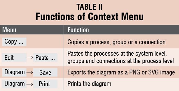
The context menu has the following functions (refer to Table II).
 The main toolbar(7) consists of options for creating a new system, opening an existing system, saving the system, and running the simulation.
Filter(8) can be used to search for elements directly in the browser.
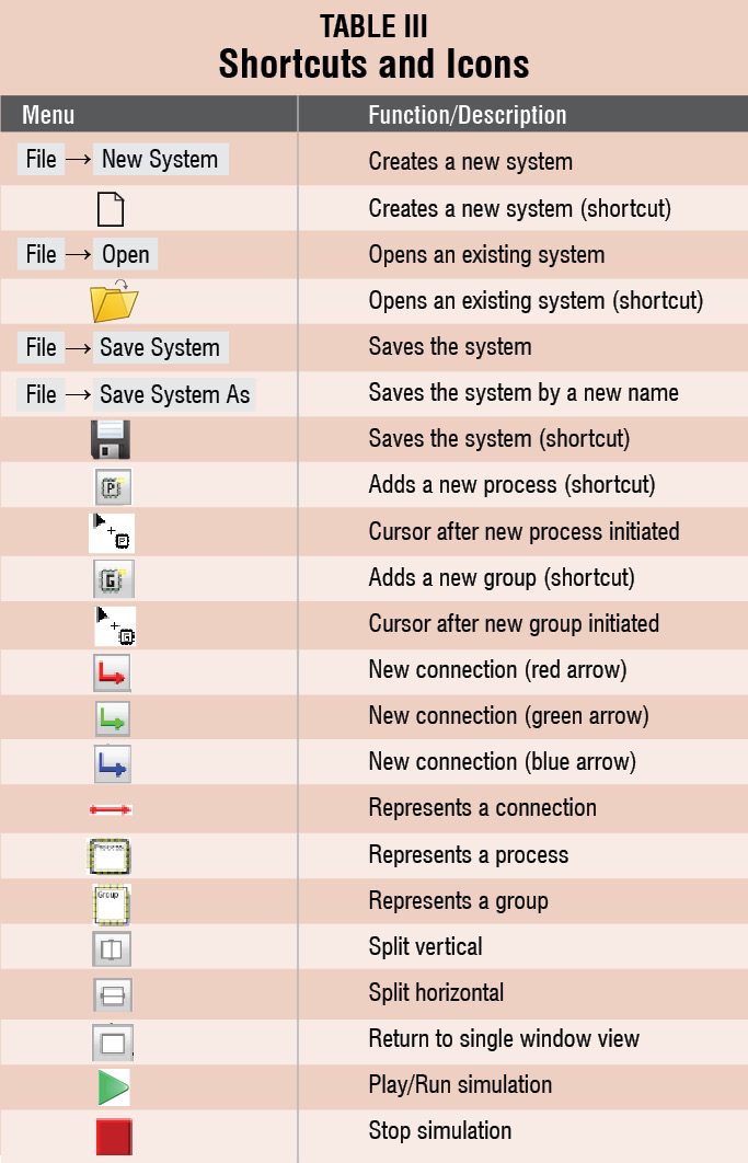
3. Creating a new system: To create a new system, select File→New System via the menu or shortcut button from the main toolbar(7).
4. Opening an existing system: An existing file system is opened by selecting File→Open via the menu or shortcut button from the main toolbar(7).
5. Saving the system: Press the shortcut button on the main toolbar(7) or select File→Save System via the menu. To save it by a new name, select File→Save System As via the menu.
6. Creating a new process: To add a new process to the system, first activate the system level by clicking on the leftmost tab in (2) or double click on the system node in browser(6), and then click on the new process button in diagram editing toolbar(3). The cursor will change and left clicking in the diagram editing plane will put the new process. Right clicking in free space will abort the action.
7. Creating a new group. To add a new group to a process, first activate a process by clicking on the corresponding tab in (2), or double clicking on the process node in browser(6) and then clicking on the new group button in diagram editing toolbar(3). The cursor will change and left clicking in the diagram editing plane will put the new group. Right clicking in free space will abort the action.
8. Creating a new connection. To add a new connection, click on the corresponding button in (3). The red arrow will create an excitatory connection, the green arrow will create a modulatory connection and the blue arrow will create an inhibitory connection. To position any connection, first click on the edge of the source and target group icons. Group icons are yellow squares.
For creating connections among groups of different processes, first split the diagram editing pane into two views by using the Split Vertical and Split Horizontal buttons in (5). Then use (2) to display each separate view of the diagram editing pane of one of the processes containing the group you want to connect to. Finally, connect the two groups by the process described above. Return to the single-window view.
9. Simulating the system: To simulate, click on the Play button on the main toolbar(7). A warning will pop up if there is some inconsistency in the model. This can occur if any connection target is not defined.
To stop the simulation, press the Play button again.
Download the latest version of the software: click here
The author is a tech journalist at EFY Gurgaon


