
When waking up at night to use the wash basin, you may struggle to find the switchboard to turn on the light before opening the wash basin tap to wash your hands. To help, this automatic wash basin tap with built-in LED light has been designed using an IR module and 555 timer IC. The IR module is a very simple and compact device, which has transmitting and receiving IR LEDs and a comparator.
This device opens the wash basin tap automatically and switches on the LED light fitted above the wash basin when one reaches in front of the wash basin. The wash basin tap and the LED light turn off automatically after a set time.
| Parts List | |
| Semiconductors: | |
| IC1 | -LM7805, 5V voltage regulator |
| IC2 | -NE555 timer |
| T1, T2 | -BD139 npn transistor |
| BR1 | -1A bridge rectifier |
| D1 | -1N4007 rectifier diode |
| LED1 | -5mm LED (green or red) |
| LED2-LED10 | -5mm white LED |
| Resistors (all 1/4-watt, ±5% carbon): | |
| R1-R3, R8 | -1-kilo-ohm |
| R4 | -270-kilo-ohm |
| R5-R7 | -470-ohm |
| Capacitors: | |
| C1 | -1000µF, 35V electrolytic |
| C2 | -0.01µF ceramic disk |
| C3 | -1000µF, 25V electrolytic |
| Miscellaneous: | |
| CON1 | -2-pin connector |
| SV | -12V solenoid valve normally closed type |
| X1 | -230V AC primary to 12V AC, 500mA secondary transformer |
Circuit and working
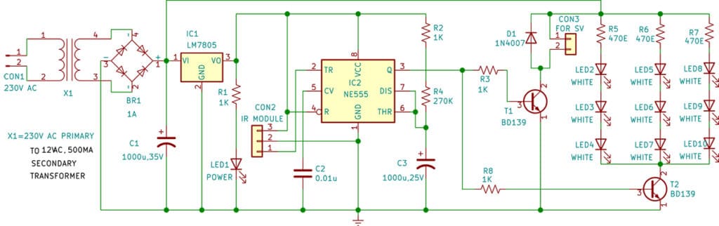
The circuit diagram of the device is shown in Fig. 2. It is built around a 230V AC primary to 12V, 500mA secondary transformer (X1), a bridge rectifier (BR1), an IR module connected across CON2, 5V voltage regulator LM7805 (IC1), timer NE555 (IC2), and a few other components.

The 230V AC mains is stepped down to 12V through the step-down transformer X1. This 12V secondary output of X1 goes to the bridge rectifier BR1. Capacitor C1 filters the ripples in voltage and the rectified output is given to regulator 7805 (IC1). IC1 provides 5V regulated DC output to enable IC2. LED1 is used as a power-on indicator.
The NE555 timer (IC2) is configured in monostable mode. The time period of IC2 is based on resistors R2 and R4 and capacitor C3, which is around five minutes in this case. By changing values of resistors R2 and R4 and/or capacitor C3, you can change the time period of IC2.

Output pin 3 of IC2 is connected to one end of resistors R3 and R8. The other end of resistor R3 is connected to the base of the solenoid driver transistor T1 to open the solenoid valve. The other end of resistor R8 is connected to the base of LED light driver transistor T2 to light up all the white LEDs (LED2 through LED10).
Normally, the IR sensor module output is high. When a person comes in front of the IR module, the sensor’s output becomes low and triggers the NE555. Its output goes high based on the timing components. Here R2+R4 and C3 are the timing components. Once the NE555 is triggered, its output becomes high for around five minutes. It performs two functions during this period.
First, it keeps the solenoid coil energised so that the valve remains open and the water keeps flowing from the tap for around five minutes. Second, it keeps the LED light on, which also remains on for about five minutes.
Construction and testing
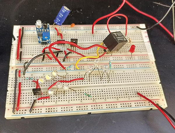
As the circuit is simple, it can be assembled on a general-purpose PCB. After assembling the circuit, enclose it in a suitable box. Install the IR sensor module in front of the hand wash sink.
Before continuing with the working of the circuit, the setup of the circuit may be understood. The IR module is fixed on the wall just above the wash basin in such a way that when no one is in front of it, IC2 does not trigger. This means that the tap and LED light fitted above the wash basin will normally be in off state when no one is in front of the IR sensor.
When someone comes in front of the IR sensor fitted above the wash basin, IC2 triggers. This activates the solenoid and water starts flowing from the tap, and simultaneously the LED light turns on, for the preset period.
Fix the solenoid valve in its proper water flow direction, which is marked on the valve housing. There is a minimum pressure required for proper functioning of the solenoid valve, for which the water storage tank should be at a height of at least three metres above the solenoid valve. Otherwise, the use of a water pressure pump would be required.
Bonus. You can watch the video of the tutorial of this DIY project.
S.C. Dwivedi is an electronics enthusiast and circuit designer at EFY