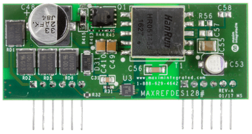
The module delivers 5V and 12.5W output from a 36V to 57V input, suitable for various development stages and power conversion.

Power over Ethernet (PoE) supplies power to devices connected via Ethernet cables, eliminating the need for separate AC power connections. This technology not only simplifies cabling but also enhances network management of devices, enables power measurement, and removes the need for AC-DC conversion in various devices such as LED lights, cameras, sensors, and more. Numerous PoE solutions utilize isolated power supplies, which ensure stable power delivery across various applications. One example is the MAXREFDES128 PoE module reference design from Analog Devices (ADI), which outputs 5V at 2.5A (12.5W) from an input range of 36V to 57V.
The module is designed for evaluation, design, prototyping, and production. It includes all necessary control circuitry and electrical components to create an isolated flyback converter power supply with a 36V to 57V input and a 5V, 12.5W output. The module is divided into two primary sections: the PD controller and the no-opto flyback DC-DC converter.
The PD controller features a PD interface controller that complies with IEEE 802.3af/at standards, providing detection and classification signatures and an integrated isolation power switch for inrush current control. It manages the detection and classification processes upon connection to PoE power-sourcing equipment (PSE). This section also incorporates a power-good (PG) signal that activates the DC-DC converter circuit, reducing startup inrush current and heat.
The no-opto flyback DC-DC converter employs a 60V peak current mode, a fixed-frequency switching controller designed for Discontinuous Conduction Mode (DCM), achieving a peak efficiency of 85% at a 100kHz switching frequency. It features a primary-side MOSFET that stores energy in the transformer’s primary winding and a secondary-side synchronous MOSFET driver that replaces the typical diode, enhancing efficiency and thermal management.
Additional module features include startup and input overvoltage protection settings, with a 5ms soft start to mitigate inrush current from the PSE. The module utilizes a resistive divider to set the switching thresholds for efficient operation.
The design is equipped with two 6-pin connectors. It incorporates two bridge rectifiers to ensure compatibility with various PSE types, though this leads to some power loss due to the continuous conduction of two diodes. Transformer specifications, such as those for the tested HR051455 from HanRun, can be calculated for custom designs with guidance from Application Note 5504. This design effectively controls the timing of MOSFET operations based on drain voltage, managing the current flow to the output load and the discharge of the output capacitors.
ADI has tested this reference design. It comes with a bill of materials (BOM), schematics, assembly drawing, printed circuit board (PCB) layout, and more. The company’s website has additional data about the reference design. To read more about this reference design, click here.


