The 10kW BLDC motor reference design features extensive protections and supports high-performance motor control for e-scooters, e-bikes, drones, and UAVs.
The demand for micro-mobility devices like e-scooters and e-bikes is growing due to the need for fuel-efficient transportation and concerns about carbon emissions. Increased adoption and development of electric powertrains for these vehicles drive this growth. The global market for electrified transportation continues to expand, and solutions like these address the rising need. Microchip’s 10kW compact BLDC motor reference design simplifies the design process.
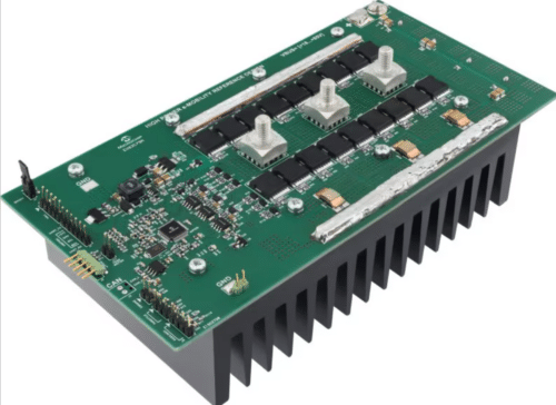
The design offers a compact, standalone motor controller solution for BLDC/PMSM motors, supporting peak levels up to 10kW and systems up to 85V. It includes various auxiliary connections for sensing and interfacing with the system.

The BLDC Motor Driver Reference Design, with its compact size, affordability, and high performance, is ideal for contemporary e-mobility motor control applications such as e-scooters and e-bikes. Moreover, it can also operate the BLDC motors in high-power drones and UAVs.
The dsPIC33CK256MP505 DSC motor controller offers up to 3kW of maximum output power, with a continuous current of 150A RMS and a peak current of 300A for approximately 120 seconds. It supports an input voltage range of 18–85V VBUS, accommodating battery packs up to 20 seconds in duration. It features an XT90-type connector for the battery pack for ease of connection.

This motor controller employs Field-Oriented Control (FOC) with HALL sensors (120°/60°) and supports multiple operating modes, including constant speed, constant torque, and constant power. Advanced features include Maximum Torque Per Amp (MTPA) for IPMSM motors and Field Weakening (FW) to extend the constant power range.
The three-phase inverter stage utilizes three MIC4101 (or MIC4104) 100V half-bridge MOSFET gate drivers and eighteen N-Channel Low RDS(on) MOSFETs (typical 1.7 mΩ), with three MOSFETs in parallel at each position. Current sensing is achieved with three low-side shunt resistors (250 µΩ) per inverter phase, and the Pulse-Width Modulation (PWM) switching frequency ranges from 8–20 kHz.
Integrated protections within the controller include safeguards against overvoltage and Undervoltage for the BUS voltage, motor phase overcurrent, inverter stage overtemperature, and HALL sensor errors. Additionally, the system features regenerative braking capability. System bias is managed through a 12V MCP16331 Buck regulator, a 5V MCP1754S-5 LDO, and a 3.3V MCP1754ST-33 LDO, with temperature measurement provided by the MCP9700A. The ATA6561 supports CAN communication, while an auxiliary connector accommodates throttle input, voltage monitoring, I2C, UART, Bluetooth, and other functions.
The EeZeeFOC Driver GUI makes motor drive optimization easier. The controller’s compact dimensions of 20 x 10 x 6 cm make it suitable for a range of applications.
Microchip has tested this reference design. It comes with a bill of materials (BOM), schematics, assembly drawing, printed circuit board (PCB) layout, and more. The company’s website has additional data about the reference design. To read more about this reference design, click here.