 We are all so busy with our daily lives that we forget to take our medicines on time, which can have several ill effects on our health. The Medication Reminder circuit described here helps in making a simple reminder that allows you to set an alert for the medicines that you need to take. The device flashes an LED or rings a buzzer at the selected time intervals. The available time intervals are matched with standard dosing times such as 4, 6, 8, 12, 24 and 48 hours for your convenience. A perfect time-interval makes this device a better choice amongst other standard reminders.
Circuit and working
The circuit diagram of the reminder is shown in Fig. 1. The circuit is built around 14-stage ripple-carry binary counter CD4060 (IC1), 12-stage ripple-carry binary counter CD4040 (IC2), dual 4-input AND gate CD4082 (IC3), quad 2-input OR gate CD4071 (IC4), dual up-counter CD4520 (IC5) and quad 2-input NOR gate CD4001 (IC6).
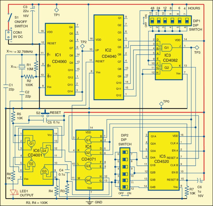
The clock for the system is provided by IC1 wired as an oscillator. This frequency is divided by 16384 (214) by the internal flip-flop chain of IC1 and a 2Hz stable clock frequency is available at its pin 3. Counter IC2 and 4-input AND gate G1 of IC3 are wired to divide the 2Hz clock by 3600. So, a pulse every 30 minutes is available at pin 1 of IC5.
Further division by IC5 is controlled by G2 of IC3 and the positions of DIP1 and DIP2 switches. The positions of DIP1 and DIP2 allow selection of 4, 6, 8, 12, 24 and 48-hour time intervals. The set-reset flip-flop formed by G1 and G4 of IC6 is set through G4 of IC4 each time a low-to-high transition is there at the pin of IC5 selected by DIP2. When the flip-flop is set, gate G2 of IC6 is enabled and the 2Hz frequency available at pin 3 of IC1 becomes available at pin 4 of IC6, causing LED1 to flash. The flip-flop can then be reset by means of S2. A master reset is automatically done at power-on by means of C6 and R7. Refer Table I for selecting the time periods.
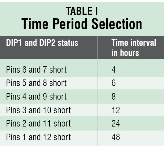
 First choose the hour interval using DIP1 and then apply power through S1. After the specified interval of time has elapsed, LED1 will start flashing at 2Hz. This status will last until pushbutton S2 is pressed, but the circuit will continue the counting and LED1 will flash again when the same hour interval as before is reached. An important feature of this circuit not found in similar devices is that the internal counter is not reset when S2 is pressed, which allows a better time-interval precision.
Construction and testing
A single-side PCB for the medicine-time reminder circuit is shown in Fig. 2 and its component layout in Fig. 3.
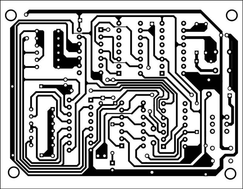
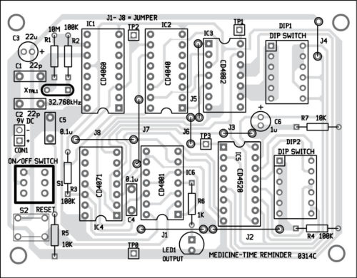
Download PCB and component layout PDFs: click here
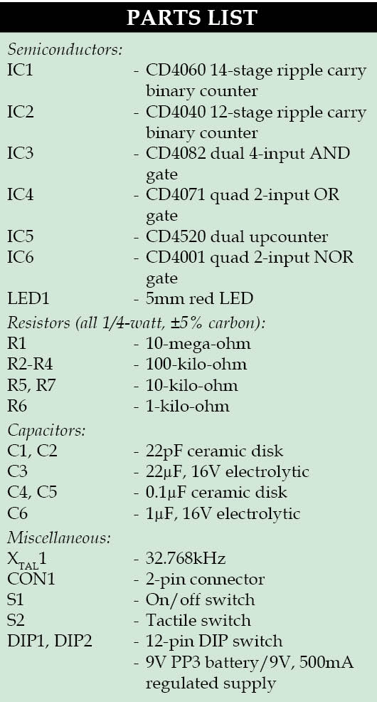
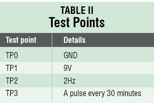
After assembling the circuit on a PCB, enclose it in a suitable plastic case such that LED1, S1, S2, DIP1, DIP2 and CON1 stick out. Verify voltage levels on various test points mentioned in the test point table before using the circuit.
The author is currently working at ESP Safety Pvt Ltd, Delhi as a senior hardware R&D engineer. His key interests are analogue circuit design and embedded systems


Sir,
Thank you for the article. I am making this project as a part of my curriculum. The working written here is nice, I have understood most of it, however I am unable to understand “Further division by IC5 is controlled by G2 of IC3 and the positions of DIP1 and DIP2 switches. The positions of DIP1 and DIP2 allow selection of 4, 6, 8, 12, 24 and 48-hour time intervals.” this particular part. It would be a great help if you could let me know more about this. Also I would like to know if other ics could be used for the same purpose and what makes these ics preferable.
Thank You !
hy chaitali i am jeet soni. i am also working on this project but i have some doubt . so please if possible then help me and try to contect by email .thankyou