


Smartphones have become a necessity in daily life. Smartwatches also help in staying connected with phones and receiving notifications. Call access is available directly through smartwatches.
Such designs have been published in EFY. A DIY article on world’s smallest phone with e-paper was previously published in EFY. A smartwatch DIY article was also published.
In continuation of these designs, the world’s smallest smartphone – IndusPhone design has now been developed. This smartphone, just 3cm in length, is somewhat the size of a smartwatch.
Since the design is somewhat complex and lengthy, it will be published in multiple parts, allowing step-by-step guidance for better understanding.
Designing
As this is to be the world’s smallest smartphone, the components must be selected carefully to fit within its small frame. The IndusBoard coin was chosen due to its compact size (around 3cm) and because it includes many I/Os required for this device.

It also integrates inbuilt sensors, such as a magnetometer, accelerometer, temperature sensor, and Wi-Fi, all within a 3cm size, helping to keep the device compact. A display of the same size with a touchscreen is also required.
Before proceeding with the design, the smartphone’s functions need to be outlined. It supports 2G and 4G SIM cards, Wi-Fi, and a touchscreen display. The basic phone functions include calls, messaging, contacts, dialling, and loudspeaker mode.
Additional features, such as games, a calculator, Wi-Fi contact sharing, Wi-Fi-based calling, and a phone finder were added after completing the design. The smartphone can be programmed with more functions, if needed.

This first part of the multi-part article focuses on designing the basic UI and testing the GSM module.
EFY note: Before proceeding with the UI code, install ESP32 on Arduino IDE. Then, install the libraries for TFT_eSPI display, GSMSim for interfacing the SIM card module, and CTS816 for using touch on the display.
| Bill of Materials | ||||||
| ID | Name | Designator | Footprint | Quantity | Manufacturer Part | Manufacturer |
| 1 | CST816 Touch Round Display Glass | CN1 | CST816 | 1 | CST816 | |
| 2 | GSM Module | M1 | SIM800LMODULE_SIM800LMODULE | 1 | 800I | SIM Com |
| 3 | MIC14 | M2 | micro-usb-smd-kh-micro0.8cb-5pj | 1 | ||
| 4 | SMD Speaker | SP1 | Speaker | 1 | gspk151035pn-8r0.5w-l35-1.25t | INGHAi |
| 5 | IndusBoard Coin | U1 | Indusboard_coin | 2 | IndusBoard Coin | IndusBoard |
| 6 | GC9A01 | U3 | GC9A01 | 1 | Waveshare | |
| 7 | SMC-204-ARP6 | U4 | SIM-SMD_SIM-SMD_MICROSIM_SMC-204 | 1 | SMC-204-ARP6 | XUNPU |
Designing UI
The basic UI will cover functions such as displaying numbers, attending calls, typing messages, and sending messages.
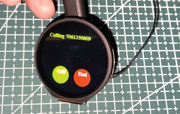
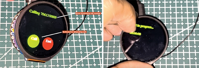
The calling UI for the incoming call screen will be designed first. The incoming call number will be displayed, and two UI touch buttons will be added for attending or cancelling the call.
The UI design will include code to display the number and two buttons with functions to detect touchpoints on the buttons displayed on the screen. Fig. 2 shows the incoming call screen UI design.
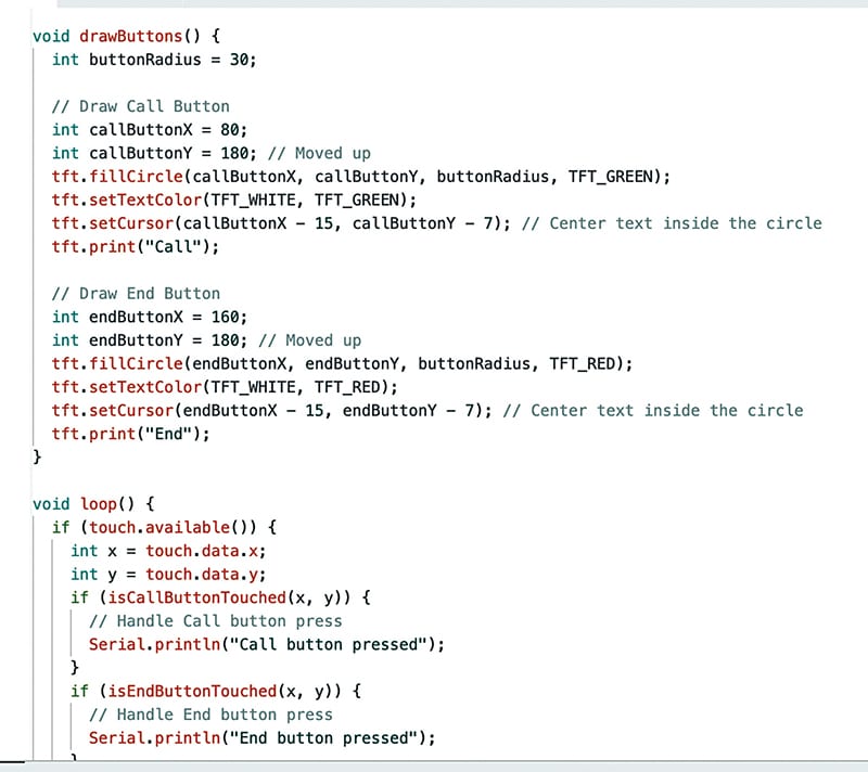
Fig. 3 shows the code snippet for the calling screen UI design.
Dialpad UI
The next step is designing the dial screen UI. Various touch buttons for different numbers will be added.
The code will check the touchpoints for each number and determine whether the touchpoint matches the range of the buttons displayed on the screen. A function will store the number as a string and display it as the dialled number.
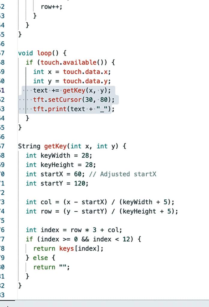
Fig. 4 shows the dial pad UI. Fig. 5 shows the code snippet for the dial pad UI design for the smallest phone.

Message Typing UI
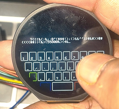
The keyboard UI will be designed to input alphanumeric characters and symbols for typing and sending messages. This process is similar to the dial pad but with more touch keys on the display.
A special key will be added to switch between alphabets, symbols, special characters, and to toggle capitalisation. Fig. 6 shows the UI for the message and keypad.
The basic UI is now ready for functions such as sending messages, dialling numbers, and checking incoming calls. The remaining UI will be covered in the next part. Now, let us turn our attention to integrating the GSM SIM card.
GSM Integration
The GSM module operates through the serial peripheral and connects to the IndusBoard coin using the serial port. The flexible I/O of IndusBoard allows the addition of many serial peripheral devices.
Defining pins in the code will enable them to function as serial pins. Most GSM modules communicate with the IndusBoard coin using AT commands, and most AT commands are standard across modules.
Functions such as adjusting volume, making calls, checking signal strength, network provider status, message storage, and more can be handled via AT commands.
Libraries simplify access to these functions, and for this device, the GSMSIM library is utilised. The code can be uploaded to make calls and check signal strength, and functions can be tested as required.
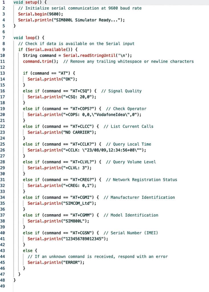
Fig. 7 shows the code snippet for testing GSM and making calls or sending messages. Fig. 8 shows the 4G GSM module.
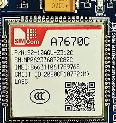
EFY note: Any 3G, 2G, or 4G GSM module can be used for the SIM card. To enable 4G functionality, the A7670C module is recommended. Alternatively, a 2G module, such as the SIM800L, can be used if 4G support is not required.
Circuit Diagram
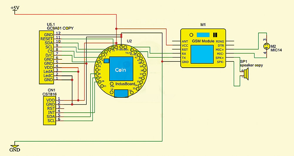
The circuit diagram for the smallest IndusPhone is shown in Fig. 9. It is built around IndusBoard coin, a GSM module, a round touchscreen display, a round LCD, and a few other components.
Construction and Testing
After gathering the components, solder them according to the circuit diagram. The display has a touch driver that operates on I2C, while the display itself works on SPI, and the GSM SIM card module functions on serial.
On the IndusBoard coin, any I/O pin can be designated for peripheral functions by defining the pin in the code.
In this case, pins 8 and 9 are used for I2C (for the display), pins 1-7 for SPI, and pins 44 and 43 for serial (for the GSM SIM module).
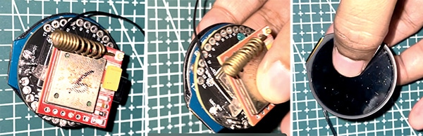
After connecting and soldering all the components, fit them behind the IndusBoard coin, as shown in Fig. 10.
Fig. 11 shows the IndusPhone components’ placement and soldering.
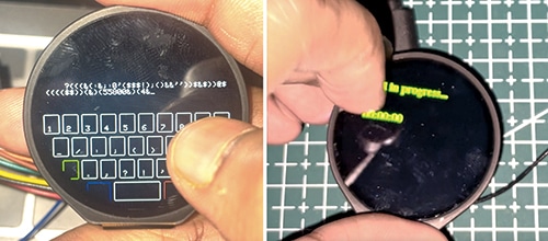
Once the device is assembled, it can be powered and tested. Each function, including the GSM SIM and the UI for typing messages, dialling numbers, and attending calls, should be tested. Fig. 11 shows the process of typing a message and dialling a number.
EFY note. This is the first part of designing the world’s smallest phone. Further parts will be published in a series, as the design is extensive and advanced.
Check the second part of making IndusPhone. Also Check the Third Part.
Bonus: You can watch the video of the step-by-step tutorial of this DIY project below
Ashwini Kumar Sinha, an IoT and AI enthusiast, is a Tech Journalist at EFY.
