


This proposed prototype works by wearing the glove and either touching a specific finger with the thumb or pressing a special switch. This action triggers a bell (buzzer) to ring automatically for 5 seconds, alerting others that assistance is needed. Additionally, the name of the requested item is displayed on the LCD screen for 10 seconds. This device has applications across various fields, including hospitals, offices, and even restaurants.
In a hospital, a caretaker assists patients with daily tasks, such as administering medicine, feeding meals, and walking. Often, an elderly patient may struggle to communicate their needs due to difficulty in expressing themselves due to illness or weakness. This device solves that issue by allowing patients to notify caretakers easily.
| List of Components | |
| Components | Quantity |
| 433MHz Tx-Rx module (RF1, RF2) | 1 |
| Decoder IC HT12D (IC1) | 1 |
| Encoder IC HT12E (IC2) | 1 |
| Arduino Uno (MOD 1) | 1 |
| 12V, 1A adaptor | 1 |
| Buzzer (B1) | 1 |
| 5mm blue LED (D1, D2, D3, D4) | 4 |
| Push to on switch (S1, S2, S3, S4) | 4 |
| 3.7V rechargeable battery | 2 |
| 3.7V rechargeable battery case/holder | 1 |
| 16×2 LCD (MOD 2) | 1 |
| 5V voltage regulator IC7805 (IC3) | 1 |
| Resistors 1-mega-ohm (R1), 47-kilo-ohm (R2, R3) | 3 |
| 10-kilo-ohm potmeter (POT 1) | 1 |
For mute patients, communication challenges can be even greater. In such cases, this device provides an effective solution, enabling patients to communicate their needs without verbal expression.

In office settings, during general meetings, ordering refreshments like tea, coffee, or snacks usually requires ringing a bell and waiting for an attendant. This process can cause delays and interruptions. With this device, orders can be placed quickly and discreetly, avoiding disruptions during meetings and saving time.
In restaurants, the device proves equally useful. With high customer volumes, waiters may struggle to serve customers promptly. When installed at tables, this system can allow customers to place orders directly to the manager or the kitchen.

The list of components required is detailed in the table.
Circuit and Working
The device consists of two main sections: the transmitter and the receiver. Their operations are outlined below.
Transmitter section: The transmitter circuit, as shown in Fig. 2, is constructed using an encoder IC HT12E (IC2), a 5V voltage regulator 7805 (IC3), a 433MHz RF transmitter (RF1), four push-to-on switches (S1 through S4), a 1-mega-ohm resistor (R1), and additional components. The transmitter operates without requiring source code.
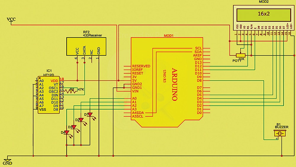
Receiver section: The receiver circuit, shown in Fig. 3, includes a decoder IC HT12D (IC1), a 5V power supply, a 433MHz RF receiver module (RF2), an Arduino Uno board (MOD1), a 16×2 LCD (MOD2), four LEDs (D1 through D4), a buzzer (B1), and other components. The receiver section must be programmed to process incoming signals and display the relevant output on the LCD while activating the buzzer. The code is written using the Arduino IDE.
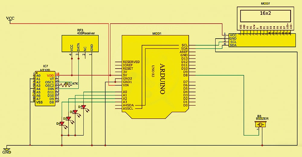
An alternative receiver circuit, which uses an I2C display, is shown in Fig. 4. The prototype for this circuit is not included.
Circuit operation
The 433MHz transmitter and receiver RF modules (RF1, RF2) allow wireless signal transmission. The system operates by interfacing the Arduino Uno, the 433MHz transmitter and receiver modules, and the LCD. When a switch is pressed (or, with the glove, when a finger touches the thumb), the transmitter sends a signal wirelessly. This signal is received by the 433MHz receiver (RF2), which is indicated by a brief blink from the blue LED. The signal is also routed to the analogue input pins of the Arduino Uno.
Upon receiving the signal, the buzzer activates for 5 seconds to notify the user. After this, the buzzer stops, and the requested item’s name is displayed on the LCD for 10 seconds.
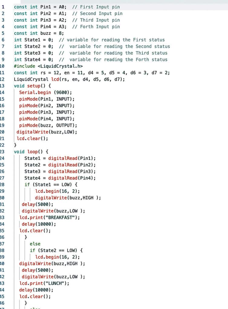
For demonstration, we programmed four messages: ‘BREAKFAST,’ ‘LUNCH,’ ‘DINNER,’ and ‘TEA/COFFEE.’ Depending on the switch pressed or the finger touched, one of these messages will appear on the LCD after the 5-second buzzer alert.
Software
The Arduino IDE (integrated development environment) is used for writing, compiling, and uploading the code to the Arduino board. The IDE comes with built-in libraries, including the LiquidCrystal library, which must be installed via the library manager. The analogue pins are then defined as input, and the pins for the LCD are configured accordingly. Fig. 4 shows a code snippet used for the LCD.
EFY note. You can also use an I2C adapter for the display, which requires I2C pins A4 and A5. Using an I2C display simplifies the connection process. If using an I2C display, adjust the code to match the setup.
Construction and testing
Assemble the transmitter circuit as outlined in Fig. 2. See the author’s prototype in Fig. 5 for guidance before starting assembly.
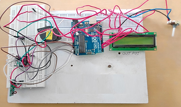
In the receiver section, remember to upload the source code to the Arduino Uno before assembly. Once the code is uploaded, assemble the receiver circuit as shown in Fig. 3. Fig. 6 shows the author’s prototype of the receiver.
After assembling both the transmitter and receiver, and verifying connections, power on both devices. Test the system by touching the appropriate points on the glove and observing the LCD output while listening for the buzzer sound.
Rakesh Jain, Assistant Professor in ECE Department in Geetanjali Institute of Technical Studies, Udaipur, holds a master’s degree in VLSI, BE degree in electronics and communication, and diploma in electronics. His research areas are sensors and microcontrollers, and he has 31 copyrights, 9 design patents registration, and 3 Indian utility patents to his credit. He is recipient of Mewar Scientist Award 2023.


Please Check Details and Circuit diagram before publish article, because in this project you circuit diagram is incomplete there is no connection between Arduino pin and RF-Decoder IC. In receiver circuit diagram also you mention wrong fig. number for Transmission Circuit in Circuit and Working Section. please check it and publish again.
Thankyou
RF D11, D10,D9,D8 connect with Arduino A0 , A1, A2, A3 . In circuit the wir colours are yello adn got match with background , we wiill update that with different colour wire connection