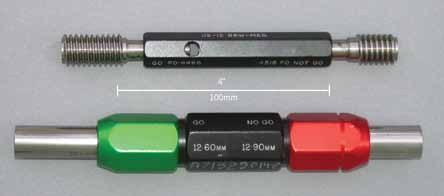
From a process point of view, there is always some risk of instruments currently in use being actually out-of-specification. Let’s take a close look at the solutions, challenges and trends in test and measurement of passive components
Ashwin Gopinath
An electronic component is any basic discrete device or a physical entity in an electronic system used to affect electrons or their associated fields. The most basic classification of electronic components—passive, active and electro-mechanical—is on the basis of energy. In layman’s terms, passive components are ones that cannot supply energy themselves, whereas a component like a battery would be called active as it truly acts as a source of energy. Let us now discuss the test and measurement solutions available for passive components.
Why test passive components
Most quality systems define actions that must be followed in case an instrument is found out-of-specification during calibration. Sometimes though, selection of test equipment to reduce the risk of out-of-tolerance condition affecting a process does not get enough credit. Cost is an important consideration, but appropriateness of the instrument to the process is critical. The instrument should meet the measurement requirements of the process not only on the day it is delivered new but also during the time period between calibrations. Unfortunately, from a process point of view, this means there is always some risk of instruments currently in use being actually out-of-specification.
Anjaneya Vara Prasad Gundu, head of process management, Cigniti Technologies, says, “Globally, the industry is actively working on designing, developing, building, enhancing and creating a good number of components/applications. With the best engineers, market competition and the right allocation of funds to research, there is no doubt that tonnes of newer components will be created and more exciting features will get added to the existing set of components in the market. However, what is quite important, yet compromised even today is ensuring some of the key attributes, viz, reliability, performance, maintainability, supportability, usability and performance, that end users are looking for in addition to low-cost components. The industry is maturing towards recognising these additional attributes that help it gain the customers’ confidence.

Solutions for test & measurement of passive components
Today, a variety of solutions for test and measurement of passive components are available in the market.
T. Anand, managing director, Knewron, explains, “Our solutions include simple testers such as Go-NoGo units or more sophisticated ones that could perform thorough testing and alignment of components/assemblies. All these solutions are either fully automated or semi-automatic, which depends upon the operating environment at the customer’s place. Some of our solutions also involve test-design for selected parts and then development of ATE for performing those tests.”
The most commonly used are Go-NoGo units, LCR meters, vector net-work analysers, spectrum analysers, data quality analysers and a number of other similar instruments. Let’s take a closer look at some of these solutions.
Go-NoGo gauge. A Go-No gauge is an inspection tool that is used to check whether a work piece is working within its allowed tolerances. The gauge derives its name from its use. It has two tests and the check involves the work piece having to pass one test (Go) and fail the other (No Go). It is one of the most basic tools, yet an integral part of the quality process that is used in the manufacturing industry to ensure interchangeability of parts in between processes.
The feature of the Go-NoGo gauge is that instead of returning a value, it returns a state. The state is either acceptable, meaning that the part is within tolerance and may be used, or unacceptable (and hence the part must be rejected).

LCR meters. An LCR meter is an electronic test equipment that is used to measure the inductance (L), capacitance (C) and resistance (R) of a component. In the basic form, the true values of these quantities are not measured; rather the impedance is measured internally and then that value is converted for display to the corresponding capacitance or inductance value. As long as the capacitive or inductive load doesn’t have a signifcant resistive component, the readings will be reasonably accurate.
In the advanced versions of the meter, the true inductance, capacitance and also the equivalent series resistance of the capacitors along with the Q-factor of the inductive components are measured.
Handheld LCR meters typically have selectable test frequencies ranging from 100 Hz to 1 kHz, 10 kHz, and 100 kHz for top-end meters. The display resolution and measurement range capability are different for different test frequencies.
On the other hand, bench-top LCR meters typically have selectable test frequencies of more than 100 kHz. They often include features that allow the user to superimpose a DC voltage or current on the AC measuring signal.


