The safety of children, elderly people, medical patients and women is a prime concern, whenever they are outside or at home alone. Nobody wants anything unfortunate to happen. The good thing is that communication networks have improved, leading to an increased usage of phones and the internet.
But what if these people wish to quickly or discreetly inform about their whereabouts for help. A smartphone is not preferable in such a situation as one has to dial a long sequence of digits.
So, in this project, you will learn to design a small SoS device like a wristwatch or any other small switch that can immediately send an SOS alert when in need of urgent assistance.
The device will be equipped with a GSM module such as SIM800L or any other microcontroller-based GSM module. At the press of a button, the person will be able to send a notification seeking help.

Bill of Material
| Components | Description | Quantity |
| IndusBoard | 3cm sized dev board | 1 |
| Battery | 3.3V | 1 |
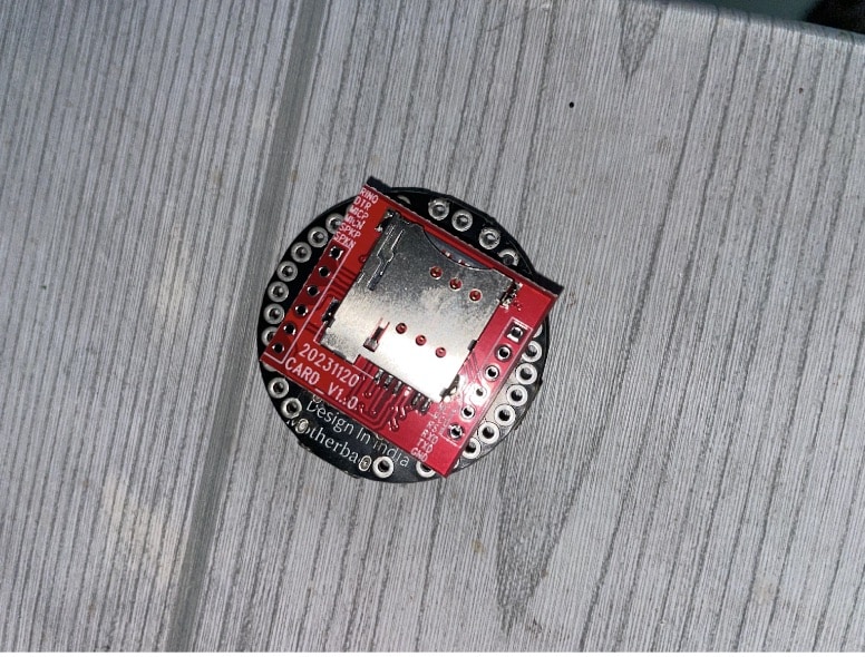
| SIM 800L | 2G GSM Module | 1 |
Programming SoS Device
You can also use a push button for sending an SOS message. However, the IndusBoard comes equipped with over 10 built-in capacitive touch sensors, which can be used as touch switches. In this example, we’ll use one of these touch switches as the input for the SOS message.
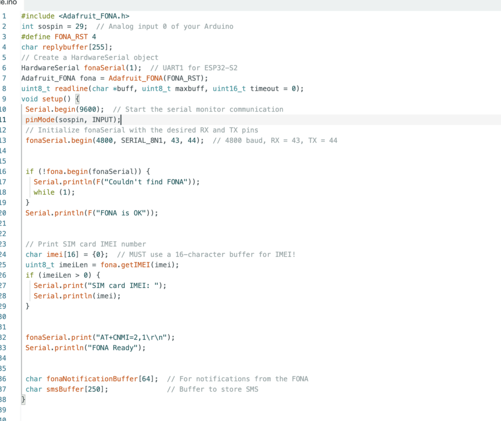
When the user double-taps or touches the specified pin, it is detected, and the SOS message is sent to the preset phone number. To achieve this, we need to define the pin as an input in the code and use the analogRead function to detect the touch.
For the GSM module, most of them operate via a serial port. The IndusBoard Coin can utilize any hardware serial port, so we specify the serial port pins in the code for the GSM module. The default baud rate for the SIM800L module is 4800, so we set the serial communication accordingly.

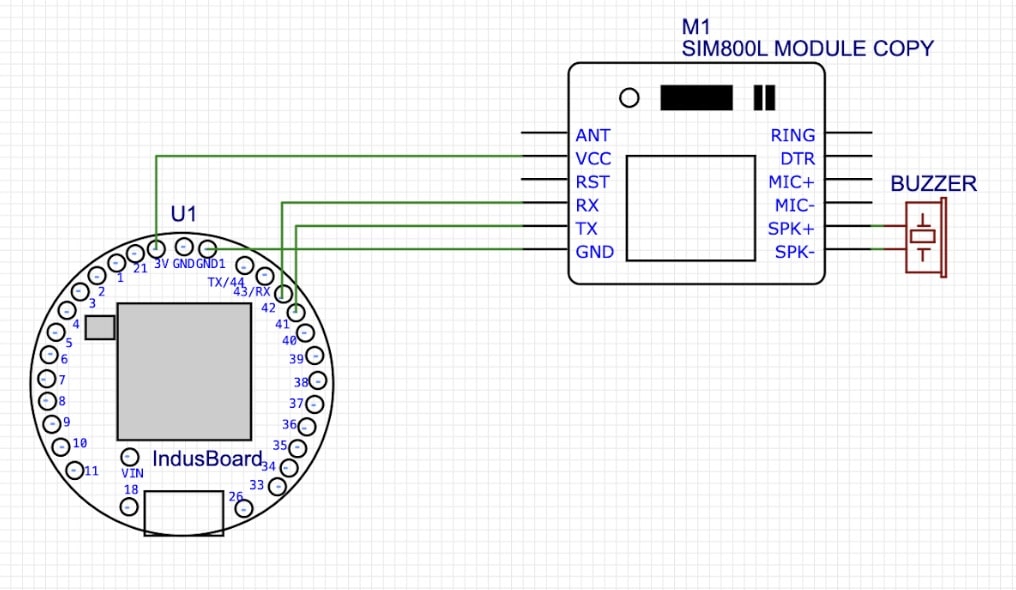
SoS Device Circuit Connection
Here the GSM module can be powered with 3.3V pin on the IndusBoard. The serial RX and TX pin connects with the pin defined in code. RST pin is optional, you can either leave it or connect it as per code. The SOS switch, you either directly use the touch GPIO or you can solder a flat metal and then use that as touch pad as per your choice. In some cases, the capacitive touchpad also works.

Testing
Now power the device either with 3.3V battery using 3.3V and GND pin on board or for testing, you can also power using USB port. Now touch the pin 21, it will send the SOS message to set number as you can see in fig below.


