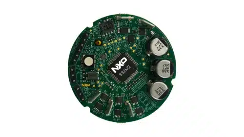
The reference design for automotive motor control combines microcontroller technology and interfaces to enhance efficiency and reduce space.

The S32M276SFFRD is a reference design from NXP Semiconductors tailored for automotive BLDC and PMSM motor control applications. It utilizes the S32M276 integrated system, which combines a 32-bit Arm Cortex-M7 S32K3 microcontroller and an analogue component that includes a voltage regulator, gate driver, and current sensor within a single system-in-package (SiP) design.
The reference design board aims to reduce both the bill of materials (BOM) and PCB dimensions. It features a compact size of less than 2 inches in diameter (5 cm) and efficiently handles BLDC/PMSM motor control applications. Furthermore, the design has various interfaces, including UART and CAN with an internal PHY, RGB LED, a JTAG 10-pin connector, faston connectors for power supply, and a 3-phase motor connection.
The design operates with an external voltage supply of +12V/5A. An internal analogue extension handles the S32M276’s power management die within the SiP, which distributes the necessary internal power utilizing the specified 12V supply. This integration not only minimizes the bill of materials but also conserves space.
The design features JTAG connectors for MCU programming via a PE Multilink Universal FX Debug Probe. This probe enables users to control the target’s execution, access and modify registers and memory values, debug code on the processor, and program internal and external FLASH memory devices. It facilitates serial and debug communications between a USB host and an embedded target processor.
The microcontroller integrates a Digital Programmable Gain Amplifier (DPGA) for low-side current measurements. This component features a digital programmable current sense amplifier with adjustable internal gain settings, a blanking time counter, and an over-current comparator, which measures the voltage drop across the current sense resistor.
The GDU features three gate driver instances, each capable of driving one high-side FET and one low-side FET. These drivers are essential for operating the three phases of a brushless DC motor. The primary function of each driver is to toggle a MOSFET between its off and on states. The pre-driver boosts control signals to the necessary levels to actuate the power MOSFET. For reliable performance, the low-side drivers are powered by the VLS regulator, whereas the bootstrap circuit directly supplies the high-side drivers.
Despite the board’s compact size, this reference design includes a BLDC motor encoder connector to enhance motor control precision. Typically, BLDC motors come with only three encoder signals in addition to the power pins. However, this design adds an extra pin to the connector. Depending on the customer’s application needs, this LED can indicate status or be used for code testing.
NXP has tested this reference design. It comes with a bill of materials (BOM), schematics, assembly drawing, printed circuit board (PCB) layout, and more. The company’s website has additional data about the reference design. To read more about this reference design, click here.


