
This Windows-based program, created with Microsoft Visual Basic (VB6), features an intuitive user graphic interface (UGI) and operates seamlessly on the Windows platform.
It interfaces with a personal computer’s (PC’s) USB port via a hardware module, which includes a microprocessor-based electronic circuit capable of controlling up to eight appliances through the PC.
The program transmits specific instructions to the microprocessor-based interface card via the USB port. These instructions are pre-programmed and stored in the microprocessor’s memory. Actions are executed through a designated relay number linked to an input/output (I/O) pin of the microprocessor and driver circuit.
At its core is the ATmega328P, a single-chip, 8-bit microcontroller housed in a 28-pin DIL package. This microcontroller is both cost-effective and widely available in the Indian market. As it is the same IC used in Arduino Uno, the ATmega328P circuit can be easily replaced with an Arduino Uno board, if preferred.
| Bill of Materials | |
| Components | Quantity |
| 220V primary to 15V, 1A secondary transformer (T1) | 1 |
| Rectifier diode 1N4007 (D1-D12) | 12 |
| Capacitor 1000µF, 25V (C1) | 1 |
| 12V voltage regulator IC 7812 (IC1) | 1 |
| 5V voltage regulator IC 7805 (IC4) | 1 |
| Relay 12V SPDT (RLY 1- RLY8) | 8 |
| Relay driver IC ULN2803A (IC2) | 1 |
| 5mm red LED for power indication | 1 |
| 1k resistor (R1) | 1 |
| Microcontroller ATmega328P (IC3) | 1 |
| 28-pin DIL IC base (optional for breadboard) | 1 |
| 18-pin DIL IC base (optional for breadboard) | 1 |
| Crystal 16MHz (X1) | 1 |
| 22pF ceramic capacitor | 2 |
| USB-to-TTL serial converter (see Fig. 2) | 1 |
| Jumper wires | As required |
| Relay connectors | 8 |
The Arduino IDE, required to program the ATmega328P, is available for free download at https://www.arduino.cc/en/software. A block diagram illustrating the program’s functionality is shown in Fig. 1, while the complete bill of materials is provided in the table on this page.
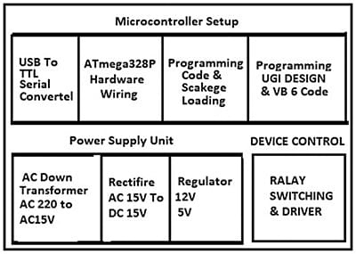
This program involves using Visual Basic (VB) to communicate with an external hardware module through the USB port. A basic understanding of VB programming and hardware knowledge for connecting and controlling the hardware module is necessary. A microcontroller or USB interface module acts as the intermediary between the PC and the appliances.
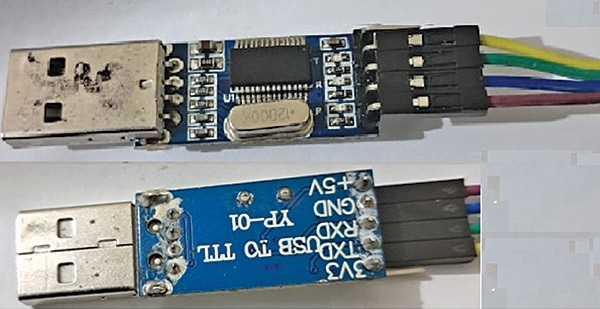
The appliances are connected via relays. A general-purpose PCB or breadboard, jumper wires, and a power supply for external appliances are used. Fig. 2 shows the USB-to-TTL serial converter used to program the microcontroller ATmega328P.
Circuit and Working
Appliance control through the PC’s USB port using Visual Basic is illustrated in Fig. 3. The circuit comprises a step-down transformer, 12V voltage regulator LM7812 (IC1), bridge rectifier, relay driver UL2803 (IC2), microcontroller ATmega328P (IC3), 5V voltage regulator 7805 (IC4), 12 rectifier diodes 1N4007 (D1-D12), eight 12V SPDT relays, a 16MHz crystal, and other supporting components.
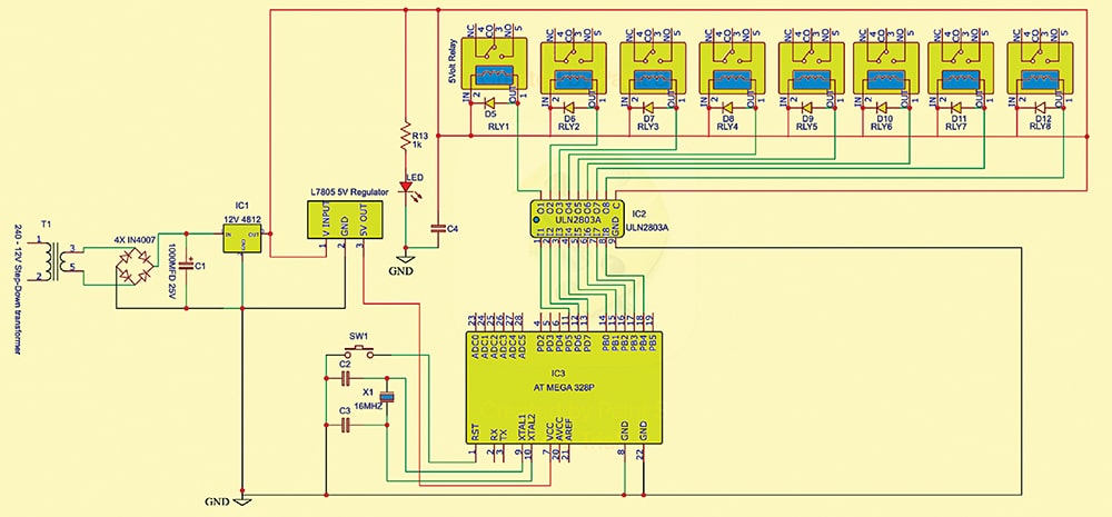
The LED indicates whether the circuit is powered. A 12V and a 5V regulated power supplies are required to operate the circuit. These are derived from a 220V AC primary to 15V, 1A secondary transformer (T1), a bridge rectifier built with four 1N4007 diodes (D1-D4), and 7812 and 7805 voltage regulators.
Capacitor C1 removes ripples. The 12V output from IC 7812 powers the relays and provides input to IC 7805, whose 5V output enables the ATmega328P.
The microcontroller’s output pins are directly connected to ULN2803A pins as per the circuit diagram to control the appliances via relays. The ULN2803A relay driver isolates the low-voltage circuit from the high-voltage section and controls the relay contacts.
Software Programming
Install the IDE for VB development. Ensure proper USB drivers for the microcontroller or interface module. Include libraries for USB communication. Use input-output ports for serial communication. Two programs are used:
1. Arduino code sketch for the microcontroller (Fig. 4).
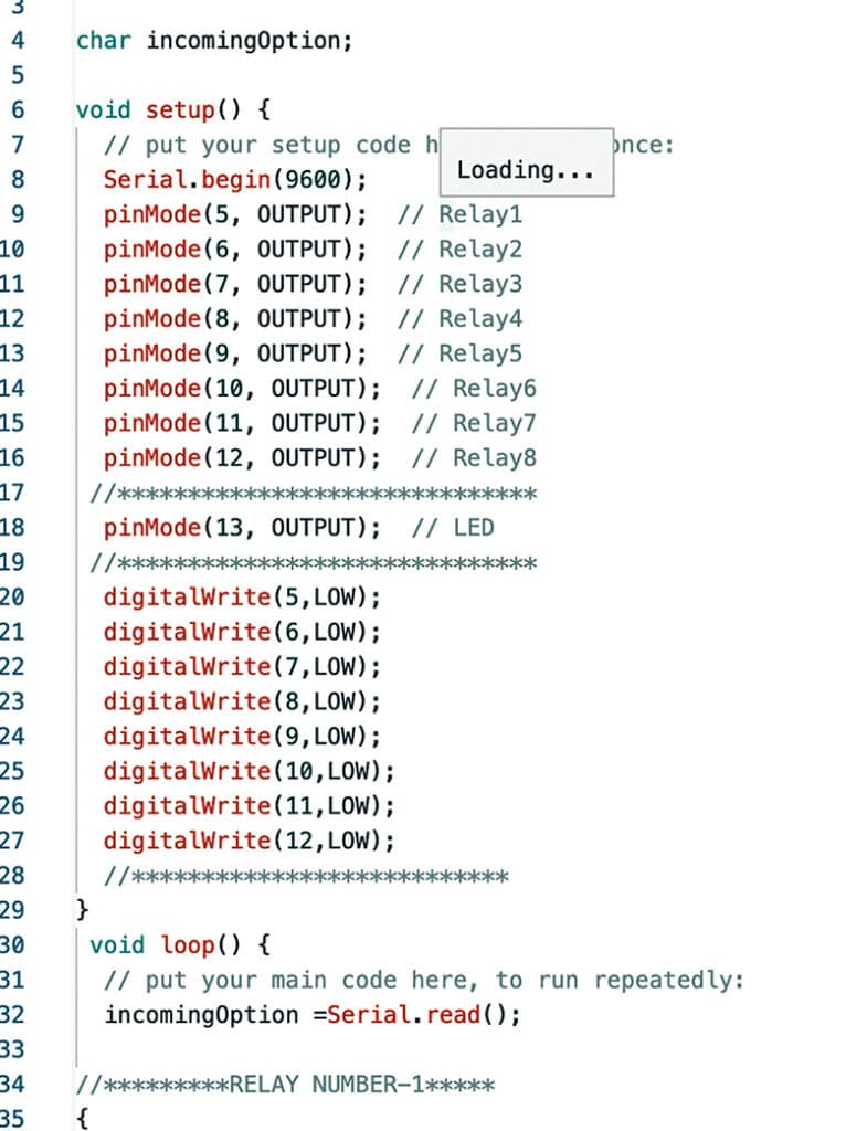
2. Visual Basic-based GUI for the PC, providing a graphical interface to control the appliances via the serial port.
Programming Procedure
- Assemble the circuit according to the diagram on a breadboard or zero PCB. Verify all connections.
- If programming through Arduino Uno, the USB-to-TTL serial converter is unnecessary.
- After programming, remove the ATmega328P IC from the Arduino Uno board and insert it into the breadboard during assembly. Add a new ATmega328P to the Arduino board.
- Run the Arduino IDE program on the PC.
- If not using an Arduino Uno board, use a USB-to-TTL serial converter card to program the ATmega328P. Connect the receiver pin (RXD) of the converter to the transmitter pin (TXD) of the microcontroller, and vice versa.
- Identify the Arduino port in the PC’s device manager. Open the IDE, navigate to ‘tools,’ and select the appropriate board and port.
- Open a new sketch in the IDE, copy the code, paste it, verify it, and upload it to the ATmega328P microcontroller with a bootloader.
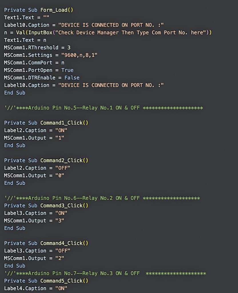
VB6 Programming for Creating GUI
Set up Visual Studio and create a new window. Add controls and the SerialPort in the toolbox. Write the VB code. Run VB6 on the PC, copy the VB6 program (Fig. 5), paste it into the new project, and create an executable (EXE) file.

Construction and Testing
After programming the ATmega328P IC, remove it from the Arduino Uno board. Assemble the circuit and use the programmed IC as shown in Fig. 3. Press F5 to run the VB application. Ensure the correct COM port is specified. Use the Arduino IDE’s serial monitor to verify commands and responses, if needed.
Power the hardware, connect the FTDI or Arduino Uno to the PC’s USB port, and run the GUI Visual Basic code. The GUI will appear on the screen (Fig. 6). Control the appliances by clicking the GUI buttons.
Adeeb Raza is an electronics engineer with about 35 years of practical experience. He is a regular reader and contributor to EFY.


