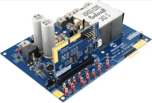
The design maximizes efficiency with a scalable battery charger design. It supports various panels, chemistries, and power ranges for outdoor applications.

Solar Maximum Power Point Tracking (MPPT) battery charger reference design from Microchip is optimized to extract the most power from solar panels in different lighting conditions, shading, temperature changes, and sun angles. It ensures safe battery charging with predefined profiles and works with various battery chemistries and solar panel types. This makes it suitable for powering streetlights, road signs, portable generators, cooling fans, and consumer electronics in RVs.
Engineers can quickly use this open platform to develop a solar charger using synchronous buck topology. The design supports a power range of less than 20W to over 400W, making it highly scalable. The PCB is designed with optional footprints for input/output capacitors, sync-buck MOSFETs, and inductors, allowing engineers to customize their setup. Additional features, such as battery and output load current/voltage/power metering (for fuel gauging), temperature monitoring, and automatic cooling fan control, can be added or removed based on the specific requirements of the end product.
The included firmware provides an open development platform, simplifying the integration of charging algorithms, safety features, I2C interfaces, and power-point tracking algorithms. These functions are implemented as state machines, called from a simple main loop, and can be updated or replaced as required. The hardware is fully abstracted from the state machines, enabling easy configuration and customization. A Windows-based GUI allows complete control and configuration of the board via a single USB connection, with live updates of all parameters shown numerically and graphically throughout the charge cycle.
The design offers several benefits, including compatibility with solar panels with output voltages ranging from 15 to 60 V. It provides flexibility in delivering output power between 10 and 400 W and can connect to either a single solar panel or series and parallel connected arrays. MPPT ensures the most efficient operating point for the solar panel. Additionally, it supports charge profiles for multiple battery chemistries, further enhancing its versatility.
The CSM controls the system by moving through different steps to charge the battery safely. There are separate state machines for each type of battery, which can be turned on using settings. Each step controls the hardware to ensure the right amount of current and voltage is given to the battery, then moves on to the next step. Each type of hardware may need changes to these functions to work correctly.
The MPPT Solar Charger evaluation board is pre-calibrated for the right voltage and current ranges for each board. If the solar input range or battery setup changes, you can adjust the voltage dividers and current monitoring resistors to use the controller’s ADC range fully. In production, each board needs to be calibrated using a precision voltage and current source that matches the final product’s input and output voltage range.
Microchip has tested this reference design. It comes with a bill of materials (BOM), schematics, assembly drawing, printed circuit board (PCB) layout, and more. The company’s website has additional data about the reference design. To read more about this reference design, click here.


