 Bedwetting is one of the most common childhood problems that can have a significant impact on a child’s health if left unattended. During the night, the parents would not know if the child has urinated and the kid may sleep all night long on a wet bed. Bedwetting alarm provides a very effective solution to this problem. The alarm will sound as soon as the child begins to wet the bed.
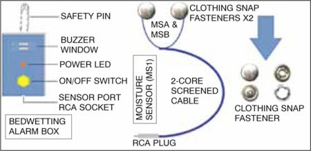
The alarm can also be very helpful for physically challenged people, hospital patients and people suffering from nocturnal enuresis. The bedwetting alarm’s special moisture sensor (wet sensor) placed on the bedsheet near the child triggers an alarm at the start of urination. The alarm’s sound is loud enough to awaken the child and the parents, who can take the child to the bathroom and the wet clothes of the kid can be changed before going back to sleep.
A thin cable runs from the moisture sensor to the audio alarm unit, which is attached with a safety pin to the bed sheet as shown in Fig. 1.
Circuit and working
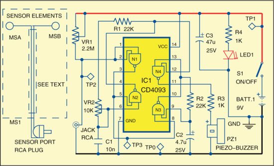
The circuit is a battery-operated audio alert signal generator built around a popular quad two-input CMOS NAND gate with Schmitt trigger IC CD4093 (IC1). The circuit of the bedwetting alarm is shown in Fig. 2.
In this circuit, gate N1 of IC1 is used to check the status of moisture sensor MS1. Variable resistor VR1 works as a sensitivity-control preset. If the sensor is wet, the input of N1 drops to low level. A gated oscillator is implemented to produce a pulsed tone to drive the piezoelectric audio alarm using gates N2, N3 and N4. Current consumption of this circuit on standby is very low, thus allowing the use of a 9V compact battery to drive the circuit for many months.

A pair of commonly available clothing snap fasteners (MSA and MSB) can be used as moisture sensor MS1. Attach the sensor elements to the bed sheet such that the bed sheet is between MSA and MSB.
Working of the circuit is simple. When the child urinates, the bed sheet becomes wet allowing conduction between MSA and MSB terminals. This provides a low level at the input of N1 that triggers the oscillator and the buzzer turns on.
Construction and testing
A single-side PCB for bedwetting alarm is shown in Fig. 3 and its component layout in Fig. 4. After assembling the circuit on a PCB, enclose it in a suitable case that should have an opening for the RCA socket, on/off switch, LED1 and buzzer as shown in Fig. 1.

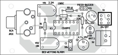
Download PCB and component layout PDFs: click here
The gap between the MSA and MSB should not be more than 50 mm. Use any twin-core screened cable for interconnection between the moisture sensor and the audio alarm generator. Note that it is possible to replace the sensor elements (MSA and MSB) of moisture sensor MS1 by other thin conductive fasteners or foils.
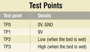
To test the circuit, trigger switch S1 and check various voltages as shown in the table. Status of LED1 indicates the availability of 9 volts, which can also be verified at TP1 with respect to TP0. TP goes low when the bed sheet between MSA and MSB is wet, triggering the oscillator, which can be verified at TP3.
The author is a regular contributor to EFY. He is a freelance electronics circuit designer and technical writer


