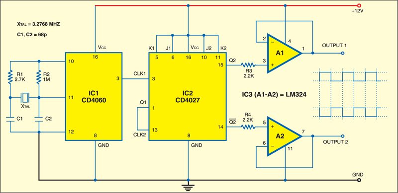
 Here is a simple crystal based 50Hz generator circuit that generates 50Hz frequency using a crystal. It produces alternating 50Hz pulses with 50 per cent duty cycle, which can be used in inverter circuits. It comprises a 14-stage counter and oscillator (CD4060), dual J-K flip-flop (CD4027), operational amplifier (LM324) and a few discrete components.
Crystal based 50Hz generator circuit
The oscillator is built around IC CD4060 (IC1) using a 3.2768MHz crystal. Resistor R1 is used to limit power. R2 is the biasing resistor. For starting and maintaining oscillations, a minimum transconductance is necessary, which is provided by R1.

The oscillator frequency is divided by ‘14’ to get 200 Hz at pin 3 of CD4060. The 200Hz frequency is further divided by ‘4’ with the help of a dual JK flip-flop CD4027. 50Hz frequency is thus generated at pin 15 and complement of this frequency is generated at pin 14 of CD4027. The duty cycle of the generated frequency is 50 per cent.
The 50Hz frequency is buffered by operational amplifiers A1 and A2 of LM324. The square wave outputs in opposite phase available at pins 1 and 7 of the operational amplifiers find application in inverter circuits.
Assemble the circuit on a general-purpose PCB and enclose in a cabinet with enough space for the battery and switches. Connect a 12V AC adaptor or 12V battery for powering the circuit.
Feel interested? Check out other electronics projects.
The article was published in January 2008 and has been updated recently.


Why Xtal is used and how???
I want 1Mhz & 3 MHz output , is it possible from this circuit ?
Then what will be the values of R1 R2, & C1 C2 ?
I made this schematic several times and i don’t have 50Hz. I don’t know why. I checked my circuits A LOT and nothing.
@Trajectory, because 3.2768M/14 is not 200