 AC switches are silicon devices that control AC loads directly connected to the AC mains. This means that the driving reference terminal of the AC switch can be connected to the Line potential. This circuit explains the need for an insulation layer for the control unit and the way to implement it for an AC switch device.
It was thought in the past that connecting an MCU to the Line should be avoided as it will lead to poor appliance immunity. But it has been demonstrated over the years that such topology provides good immunity. Connecting an MCU supply to a stable non-floating reference is even better for immunity.
Safety insulation should be provided between accessible parts and high-voltage circuits to protect end users against electric shocks. It’s not required to ensure safety insulation by insulating low-voltage control circuits (like MCU) from high-voltage parts (like AC switches). In fact, the insulation could be implemented elsewhere—for example, on the keyboard to which the end user has access—leaving the MCU connected to the Line. This could be cost-effective as a non-insulated power supply and non-insulated drivers would then be sufficient.

Operational insulation is required when the control circuit reference is not the same as the AC switch reference. This is the case with new appliances using an inverter for 3-phase motor control, where the MCU is connected to the DC rail and the AC switch is referenced to Line. A level-shifter is used to allow communication between the MCU and the power switch. A usual way to implement this is to use an opto-triac but such a device will not work properly for all AC switches.
Among AC switches available today, different technologies and designs are used. The main known families are the standard triacs, the snubberless triacs and ACS devices.
To switch-on a triac or an ACS device, a gate current must be applied between the gate (G) and terminal A1 for the triac, or between gate and terminal COM for the ACS device.

For the triac, the gate current could be positive or negative, but the silicon structure of an ACS device is different from a triac. Here the gate is the emitter of an npn bipolar transistor. So there is only one p-n junction. The gate current can then only be sunk from the gate, not sourced to it.
As ACS devices can be triggered only by a negative current, an opto-triac will drive the ACS device only when the Line voltage is negative. This will lead to half-cycle conduction, which is inconvenient for most applications. However, there are new applications where such an operation is requested—for example, pumps used in coffee machines that feature an internal diode, and electromagnets used for door-lock function in washing machines.
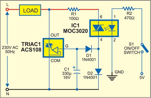
As shown in Fig. 1, the circuit is built around ACS108 (Triac 1), opto-triac IC MOC3020 (IC1) and a few discrete components. Working of the circuit is simple. When you press switch S1, the load is switched on. When you release switch S1, the load turns off.
Once the switch is pressed, the opto-triac (IC1) conducts to charge capacitor C1 up to VGT (about 0.7 volt). COM-G junction forward-biases, triggering the ACS device by a negative gate current. The ACS device will remain ‘on’ up to the next zero-current crossing point. G-COM voltage is down to –0.7V due to ACS device conduction and the capacitor remains charged. As the current through the ACS device increases, VG-COM increases and there-fore a negative current is applied by C1 which triggers the AC switch for the next cycle.
In this solution, the ACS device is ‘off’ at the beginning of each time cycle required to recharge capacitor C1. The ACS device turns ‘on’ when the voltage across its terminals equals approximately 10V. This behaviour doesn’t result in high conducted noise as the Line current is still approximately sinusoidal due to the charge current flowing through capacitor C1 at zero-voltage crossing point.
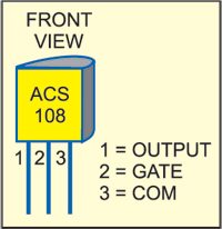
Assemble the circuit on a general-purpose PCB and enclose in a suitable cabinet. The pin configuration of ACS108 is shown in Fig. 2. Fix switch S1 on the front panel, and two terminals for the load on the rear side of the cabinet.


how can control fan speed using triac without programing (PIC)
The capacitor C1 should be connected with the + to the N and – to the gate of opto TRIAC.
you are right. diode is there so how c1 get charged. either diode polarity is wrong or c1 capacitor polarity is need to change.
We need to control 3phase 7hp pumps using microcontroller
Pump also have their own starters
So it draws very high current at the beginning
Are the diodes polarity is correct?