 Two-way switches, more profoundly known as staircase switches, are widely used when a load has to be controlled from two ends of the location. For example, a staircase lamp that needs to be con-trolled from both ends of the staircase, or a hallway or corridor light that needs to be controlled from both ends of the halfway.
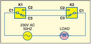
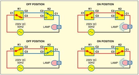
Fig. 1 shows the two-way switching arrangement. K1 and K2 are single-pole, double-throw (SPDT) switches that are installed at the two ends of a location. Fig. 2 shows the switching mechanism for ‘on’ and ‘off’ states of the load.


In home appliance automation, switching is usually controlled by a microcontroller. The output of the microcontroller is used to control the operation of the relay for switching the electrical appliance.
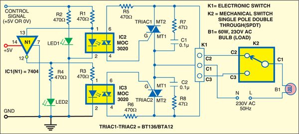
Fig. 3 shows the complete circuit for two-way switching. The appliance can either be controlled by mechanical switch K2 or solid-state switch K1. Switch K1 can be either electronically controlled or computer-controlled.

The 230V AC live (L) wire is connected to C1 terminal of switch K2 through bulb B1. When a high logic (5V) is applied at pin 1 of IC2 through the control signal from the microcontroller, the internal LED of opto-isolator IC2 (MOC3020) glows. As a result, TRIAC1 fires and the phase voltage (230V AC) becomes available at terminal C2 of K1, causing bulb B1 to glow. LED1 indicates that opto-isolator IC2 is active. Hex inverter N1 (IC1) ensures that either IC2 or IC3 is activated at any given time.
When a low logic (0V) is applied to pin 1 of IC2 through the control signal from the microcontroller, opto-isolator IC2 deactivates but opto-isolator IC3 activates through the inverter output (pin 12) of gate N1 (IC 7404). This is indicated by LED2. Thus when the control signal from the microcontroller is high/low, the phase volt-age (230V AC) is present on C2/C3 terminal of K1. This is interfaced to the electrical appliance (lamp, fan, motor) with mechanical switch K2.
Thus the electrical appliance can be operated either electronically by applying logic high or low to the control signal, or by the mechanical switch, which can be mounted on a wall traditionally.
Resistor R7 in series with capacitor C1 across TRIAC1, and resistor R8 in series with capacitor C2 across TRIAC2 form snubber circuits, which ensure that switching of the inductive load does not create peak voltages across the TRIAC terminals. Only one gate (N1) of IC1 is used here. The remaining inverters of IC1 can be used for other solid-state two-way switches not shown in the circuit.

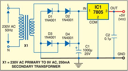
The +5V DC power supply for this circuit can be derived from 230V AC mains using the circuit shown in Fig. 4.
Assemble both the circuits (Figs 3 and 4) on a single general-purpose PCB and enclose in a suitable case. Connect mains power cord for input. Use a proper socket for the appliance and switch to enable and disable the circuit. Connect mechanical switch K2 through external wires and install the unit at a suitable place.


For automation I am using same circuit for relay as well as manual SPDT switch. But I have the problem that I didn’t get the info for, if the light is on or off in this circuit. I need the info for further processing on mcu. So, is there any other way that while using both switch as well as relay in combination I also get the info. Whether load is on or not.
This circuit can be implemented with microcontroller as suggested by you preferably using an LCD to display on or off status.
which circuit?