 There are various applications of IR sensors such as TV remote controllers, burglar alarms and object counters. Here we have used IR sensors (infrared LEDs) to make an object-detection circuit and also a proximity sensor for path-tracking robots. The basic idea is to transmit the infrared light through an IR LED, which is then reflected by an obstacle ahead and sensed by the receiving LED.
On receiving the light, the sensing LED develops a voltage difference across its leads. However, this voltage produces a very weak electrical signal. Therefore we have used an operational amplifier (op-amp) for accurate detection of the object.
Object detection circuit
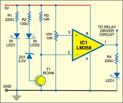
Above is the object-detection circuit. The circuit can be divided into two parts: emitter and receiver. The emitter is composed of IR LED1 in series with a 220-ohm resistor that limits the forward current. IR LED1 emits IR light continuously. The receiver is built around IC LM358 (IC1), IR LED2, Zener diode ZD1, transistor T1 and resistors R2 and R3 along with preset VR1.

According to the functioning of the op-amp, the output of IC1 will go high when the voltage at its pin 2 goes high. So the output of IC1 goes high when IR light is detected by the IR receiver. When the IR light falls on IR LED2, transistor T1 conducts making pin 2 of IC1 low. You can adjust the reference voltage at pin 3 of IC1 using preset VR1.
Working of the circuit is simple. When there is no object in front of IR LED1 and IR LED2, output pin 1 of IC1 remains low. As a result, LED1 remains off. When an object comes in front of IR LED1 and IR LED2, output pin 1 of IC1 goes high to light up LED1. At the same time, the relay-driver circuit (not shown here) is also activated.
Construction & testing
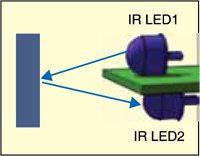
Assemble the circuit on a general-purpose PCB and enclose in a small cabinet. Mount IR LED1 and IR LED2 such that when any obstacle comes in front of them, the IR reflected off the obstacle falls directly on receiver IR LED2.
Proximity detector circuit
Below is the circuit of the proximity sensor for path-tracking robots. The circuit makes use of proximity sensors IR LED3 through IR LED6, voltage regulator LM7805 (IC2), motor-driver IC L293D (IC3), two geared motors/DC motors, 12V DC adaptor and two wheels. Voltage regulator IC2 converts the 12V DC into 5V DC. Pins 1 and 9 of IC3 are always kept high to enable the chip. Whenever inputs pins 2, 7, 10 and 15 of IC3 go high, the 12V DC (available at pin 8 of L293D) is transferred to the corresponding output pins (pins 3, 6, 11 and 14, respectively).
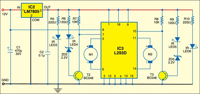
For controlling the path-tracking robot, input 1 (pin 2) and input 4 (pin 15) of IC3 are permanently held low, while input 2 (pin 7) and input 3 (pin 10) are controlled through IR sensors. Based on the output of sensor IR LED4 and sensor IR LED5, low and high voltages can be provided to input pins 7 and 10 of IC3.
As per the input combinations shown in the table, the robot will move straight, left or right. When the robot approaches a wall, the IR light transmitted by IR LED3 or IR LED6 reflects off the wall to reach the receiving LED (IR LED4 or IR LED5). This generates a low output at pin 7 or pin 10 of IC3 to stop the respective motor (M1 or M2). And when there is no reflected light, i.e., no wall, the receiving LED (IR LED4 or IR LED5) makes the output of IC3 (at pin 7 or pin 10) high to start the motor (M1 or M2).
Construction & testing
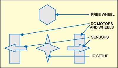
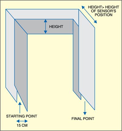
Assemble the circuit on a general-purpose PCB and enclose in a suitable cabinet. After assembling the components, fix the freewheel on the front side and the two geared/DC motors on the opposite sides as shown in Fig. 4. Fig. 5 shows the working of the path tracker.
The project was first published in November 2010 and has recently been updated.


How can I know the strength/power of a proximity sensor. I mean how can I know how far it will detect obstacle???
Proximity sensor such as IR sensor has low detection range about 3 cm to 10 cm depending on the model, manufacturer and surface of the object. You need to check it by hit and trial method.
can i replace bc548 with bc 547 , because i don’t have 548 with me now , will there any defect if if use BC547 , please suggest
Sir, why are we using IR LED 2,4 & 5 for sensing? Why can’t we use photodiode or photo transistor for sensing? Is there any advantage of using IR LED for sensing?
Dear Sir,
Using IR LEDs in desiging of the project are author’s choice.
Someone can design by using phototdiodes.
Regards