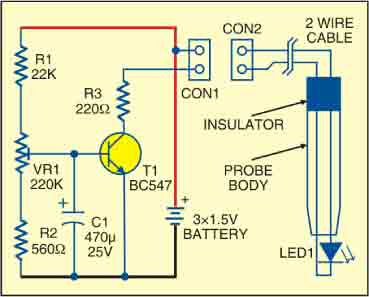
 This white LED light probe circuit is useful for inspecting narrow spaces like the inside of the CPUs, monitors, PCB modules and other electronic devices. The light source is a pencil-thin tube with ultra-bright white LED at the tip.
White LED Light Probe Circuit

The circuit is built around transistor T1 to control the brightness of LED1. The forward-bias voltage of the transistor is set using preset VR1. The centre pin of preset VR1 is connected to the base of transistor T1. Resistors R1 and R2 and preset VR1 form a voltage-divider circuit to control the brightness of LED1. Varying preset VR1 varies the forward bias voltage and thus the collector current of transistor T1. This way, the brightness of white LED1 is controlled. Resistor R3 in the collector circuit of T1 limits the current through LED1.
The ultra-bright LED requires up to 20 mA for full brightness. So there is no need for a separate on/off switch. Disconnecting CON1 from CON2 is enough when not in use.
Construction & testing
Assemble the circuit on a small piece of PCB and solder a small two-pin female connector (CON1) on its right side for connecting the probe. For the probe, use the cabinet of a plastic pen. Fit the white LED at one end and a small two-pin male connector (CON2) at the other end of the pen.
The project was first published in March 2010 and has recently been updated.


