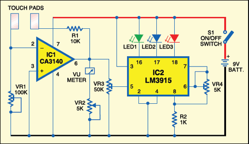
 Human skin offers some resistance to current and voltage. This resistance changes with the emotional state of the body. The skin resistance meter circuit proposed here measures changes in your skin resistance following changes in your mental state.
In the relaxed state, the resistance offered by the skin is as high as 2 mega-ohms or more, which reduces to 500 kilo-ohms or less when the emotional stress is too high. The reduction in skin resistance is related to increased blood flow and permeability followed by the physiological changes during high stress. This increases the electrical conductivity of the skin. This circuit is useful to monitor the skin’s response to relaxation techniques. It is very sensitive and shows response during a sudden moment of stress. Even a deep sigh will give response in the circuit.
Skin resistance meter
The circuit uses a sensitive amplifier to sense variations in the skin resistance. IC CA3140 (IC1) is designed as a resistance-to-voltage converter that outputs varying voltage based on the skin’s conductivity. It is wired as an inverting amplifier to generate constant current to skin in order to measure the skin resistance.

IC CA3140 is a 4.5MHz BiMOS operational amplifier with MOSFET inputs and bipolar output. The gate-protected inputs have high impedance and can sense current as low as 10 pA. This device is ideal to sense small currents in low-input-current applications.
The inverting input (pin 2) of IC1 is connected to ground (through preset VR1) and one of the touch plates, while the non-inverting input (pin 3) is grounded directly. The output from IC1 passes through current-limiting resistor R1 to the second touch plate. R1 act as a feedback resistor along with the skin when the touch plates make contact with the skin. So the gain of IC1 depends on the feedback provided by R1 and the skin.
Circuit operation
In the inverting mode of IC1, a positive input voltage to its pin 2 through the feedback network makes its output low. If the skin offers very high resistance in the relaxed state, input voltage to pin 2 reduces and the output remains high. Thus the gain of IC1 varies depending on the current passing through the skin, which, in turn, depends on the skin response and emotional state.
In the standby state, touch plates are free. As there is no feedback to IC1, it gives a high output (around 6 volts), which is indicated by shifting of the meter to right side.When the touch plates are shorted by the skin, the feedback circuit completes and the output voltage reduces to 4 volts or less depending on the resistance of the skin.
Since the feedback network has a fixed resistor (R1) and VR1 is set to a fixed resistance value, the current flowing through it depends only on the resistance of the skin. The output from IC1 is displayed on a sensitive moving coil meter (VU meter). By varying preset VR2, you can adjust the sensitivity of the meter.
For easy visual observation, an LED display is also included. IC LM3915 (IC2) is used to give a logarithmic display through LED indications. It can sink current from pin 18 to pin 10 with each increment of 125 millivolts at its input pin 5. Using VR3 you can adjust the input voltage of IC2, while using VR4 you can control the brightness of the LEDs.
In practice, the circuit provides both meter reading and LED indications. If the LED display is not needed, IC2 can be omitted.
Construction & testing
Assemble the circuit on a general purpose PCB and enclose in a suitable cabinet with touch pads glued on the top, 5-10 mm apart. Touch pads can be any type of conducting plates, such as aluminium or copper plates, having dimensions of 1XC1 cm2. The moving coil meter can be a small VU meter with 1-kilo-ohm coil resistance and 0-10 digit reading.
After assembling the circuit, adjust the presets such that IC1 outputs around 6 volts. None of the LEDs (LED1 through LED3) glows in this position with the touch plates open.
Now gently touch the touch plates with your middle finger. Maintain the finger still allowing one minute to bond with the pads and keep your body relaxed. Adjust VR3 until the green LED (LED1) lights up and the meter shows full deflection. Adjust VR2 to get maximum deflection of the meter. This indicates normal resistance of the skin, provided the body is fully relaxed.
If you are stressed or have ill feeling, skin resistance decreases and the blue LED lights up followed by the red LED along with a deflection of the meter towards the lower side. In short, the red LED and zero meter reading indicate you are stressed, and the green LED and high meter reading indicate you are relaxed. Practise some relaxation technique and observe how much your body is relaxed.
The article was first published in June 2009 and has recently been updated.


Can I somehow use this circuit to detect wire insulation resistance?
Can I use bread board instead of pcb
Yes, you can assemble the circuit on a breadboard for testing.
Could you please give the lost of components and how much will be the total budget approximately
You can build the circuit with less than Rs 500(INR)
I want to see the detected resistance values .,
So can i