Wireless Power System: An Overview
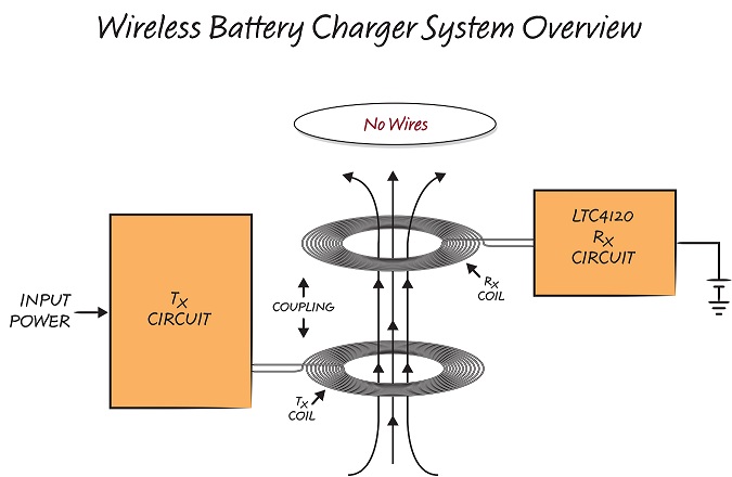
As shown in Figure 1, a wireless power system is composed of two parts separated by a gap: transmit circuitry, including a transmit coil, and receive circuitry, including a receive coil. The transmit circuitry generates a high frequency alternating magnetic field around the transmit coil. This magnetic field is coupled to the receive coil and converted to electrical energy, which can be used to charge a battery or power other circuitry.

When designing a wireless power charging system, a key parameter is the amount of charging power that actually adds energy to the battery. This received power depends on many factors, including the amount of power being transmitted, the distance and alignment between the transmit coil and the receive coil, also known as the coupling between the coils, and finally, the tolerance of the transmit and receive components.
The primary goal in any wireless power design is to guarantee delivery of the required power under worst-case power transfer conditions. However, it is equally important to avoid thermal and electrical overstress in the receiver during best-case conditions. This is especially important when output power requirements are low; for example, when the battery is fully charged or nearly fully charged. In such a scenario, available power from the wireless system is high, but demanded power is low. This excess power typically leads to high rectified voltages or a need to dissipate the excess power as heat.
How to Deal with Excess Power?
There are several ways to deal with excess power capacity when the demanded receiver power is low. The rectified voltage can be clamped with a power Zener diode or transorb. However, this solution is typically large and generates considerable heat. Assuming no feedback from the receiver, the maximum transmitter power can be reduced, but this will either limit the available received power or it will reduce the transmit distance. It is also possible to communicate received power back to the transmitter and adjust real-time transmit power accordingly. This is the technique used by wireless power standards such as the Wireless Power Consortium Qi standard. However, it is also possible to solve this issue in a compact and efficient manner without resorting to complicated digital communication techniques.
To efficiently manage the power transfer from transmitter to receiver under all conditions, the LTC4120 wireless power receiver integrates technology patented by PowerbyProxi, a Linear Technology partner. PowerbyProxi’s patented Dynamic Harmonization Control, or DHC, technique enables high efficiency contactless charging without thermal or electrical overstress concerns in the receiver. Using this technology, up to 2W can be transmitted at a distance of up to 1.2cm.
By modulating the resonant frequency of the receiver from a “tuned” condition to a “detuned” condition, DHC guarantees delivery of power under worst-case conditions without worrying about unloaded best-case conditions. This allows the LTC4120-based wireless charging system to operate over a wide transmit distance with significant coil misalignment. Furthermore, by controlling power transfer on the receiver-side only, the LTC4120-based system eliminates all potential communication interference issues, which might disrupt power delivery.
So how well does it work?
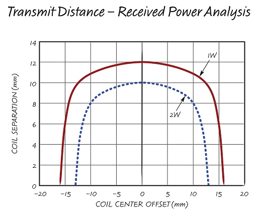
Figure 2 shows the amount of battery charge power received by an LTC4120 wireless power receiver as the separation and the center-to-center alignment between the transmit coil and receive coil is varied. With 10mm of separation, 2W of charge power is available and the coils can be misaligned significantly without much reduction in available power. While many different wireless power transmitters are available, the data in Figure 2 was generated using a basic DC-AC transmitter. The basic transmitter is an open-source reference design. Additional details for this current-fed push-pull transmitter can be found in an application note on Linear Technology’s website.

When choosing a transmitter, several factors should be considered. Is transmitter standby power (when a receiver is not present) important? Does the transmitter need to differentiate between a valid receiver and unrelated foreign metal objects? How sensitive is surrounding circuitry to EMI?
The basic transmitter is a very simple and inexpensive solution. Due to passive resonant filtering, the spectrum of EMI is well controlled at the fundamental transmitter frequency (about 130kHz). However, it transmits at full power whether an LTC4120-based receiver is present or not. Therefore, its standby power is relatively high. It also does not differentiate between an LTC4120 and foreign metal objects and can cause unrelated metal objects to warm up through induced eddy currents.
Two off-the-shelf production transmitters can be purchased from PowerbyProxi: Proxi-Point and Proxi-2D. Transmit distance and alignment tolerance performance of these transmitters is virtually identical to that of the basic transmitter. However, these more advanced transmitters can detect whether a valid LTC4120-based receiver is present or not. This feature allows them to reduce standby power if no receiver is present and terminate power transmission if unrelated foreign metal objects are nearby.


