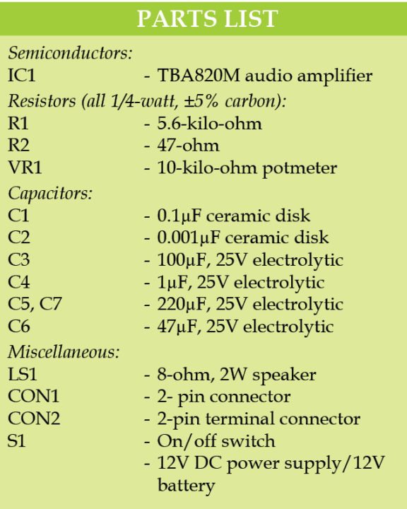
Here is a simple AF amplifier project based on TBA820M IC. This amplifier can deliver two-watt output power with 8-ohm speaker using a 12V power supply.
A 3-16V battery or an AC/DC adaptor can be used to power this circuit. Author’s prototype is shown in Fig. 1.
Circuit and working


Circuit diagram of the two-watt TBA820M AF amplifier is shown in Fig. 2. An 8-ohm, 2W loudspeaker is connected to output pin 5 of IC1 through C5.
Pin 8 (ripple rejection) is connected to +Vcc through C6. Also, C7 is connected to positive and ground for noise filtering.
Construction and testing on AF Amplifier


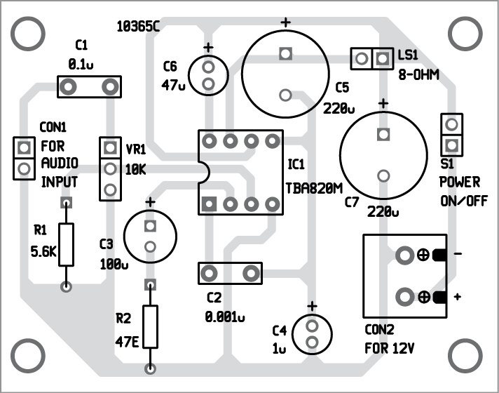
An actual-size, single-side PCB pattern for the amplifier circuit is shown in Fig. 3 and its component layout in Fig. 4. A general-purpose PCB or veroboard can also be used to build this circuit.
It is better to use an IC socket for the IC. After assembling the circuit on the PCB, enclose it in a suitable plastic case.
 For input and output connections, you may use 2-pin connectors. This will make the project neat and clean for easy connections.
After assembling the circuit, calibrate the circuit. For calibration, connect a 12V battery. First, check correct polarity of the power supply and then switch on S1. Then, connect the speaker to output of the circuit. Set potmeter VR1 to its mid position.
Take a small screwdriver and gently touch input pin 3 of TBA820M. You will hear a humming sound from the speaker if the circuit is working. Connect audio source like MP3 player or mobile phone at CON1. Adjust volume control VR1 until you get a loud and clear sound.
DOWNLOAD THE PCB AND COMPONENT LAYOUT PDFs: CLICK HERE
Raj K. Gorkhali is a regular contributor to EFY. His interests include designing electronics circuit


I want the working of it
can you tell me the part name and footprint of TBA820M audio amplifier. I am trying to find in capture but i cant find that part.
What’s the use of resistor R1 (5.6K) connected across pin 3 & ground ?
Very Simple Circuit.
What’s the use of resistor R1 (5.6K) connected across pin 3 & ground ?