Most of the low cost digital oscilloscopes and voltmeters have input resistance around 1 MOhm and input capacitance around 100pF. But in many case we are in need of input resistance above 10 MOhm and input capacitance of below 20pF. That is the case when we wish to see and measure signal from high impedance buffers as filters and some sensors. Most of the signals in the electronic circuits are in the range of +-15V and can be captured with popular operational amplifiers.
Modern op-amps can drive loads of 2 kOhm and that is enough for most digital and analog oscilloscopes and voltmeters. Also we are in need to capture differential signals with low voltage levels. That can be the case of components in the electronic circuits which are not connected to the ground.
For that purpose we are in need of high impedance buffers which convert the differential signals into normal signals with reference to the ground. The industry offers some electronic buffers, pre-amplifiers and active probes with high impedance for oscilloscopes and voltmeters. But they are relatively easy to be damaged and are expensive to be repaired or replaced. They are not suitable for the hobbyist and many educational institutions in the field of electronics.
That paper is describing two simple and low cost high impedance buffers which solve the problems described above. The bandwidth of the buffers can be more than 1 MHz and depends mainly on the operational amplifier. Also during the practical exercises with students the equipment is frequently damaged due to inappropriate usage. The proposed buffers works also as protection blocks for the expensive oscilloscopes and voltmeters.
Buffer with four channels

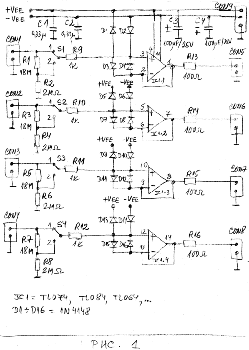
Figure 1 : presents the schematic diagram of the high impedance buffers with four channels and with unity gain for each channel. The buffer is used mainly for multi-meters and oscilloscopes. Each channel of the pre-amplifier has unity gain.
The input signals are applied to the connectors CON1, CON2, CON3 and CON4.
The input resistance of each channel is 20MOhm.
The switches S1, S2, S3 and S4 can reduce the input voltage 10 times if needed
The diodes D1 to D16 protect the inputs of the operational amplifiers.
The pre-amplifier is build around quadruple single op-amp.
This makes the circuit with lowest price and with possible smallest size. Some of the op-amps appropriate for the buffer are listed in Table 1.
| Operational amplifier | Bandwidth, MHz |
Offset voltage, mV, (typical – maximal) |
Noise, nV/sqrt(Hz) |
Standby current, mA, (typ – max) | Typical slew rate, V/us |
| TL074 | 4 | 3.0 – 10 | 18 | 5.6-10mA | 13 |
| TL084 | 4 | 5.0 – 15 | 25 | 5.6-11.2mA | 13 |
| TL064 | 2 | 3.0 – 15 | 47 | 0.8-1.0mA | 6 |
Table 1. Some operational amplifiers appropriate for the buffers in the article
Dual buffer with differential inputs
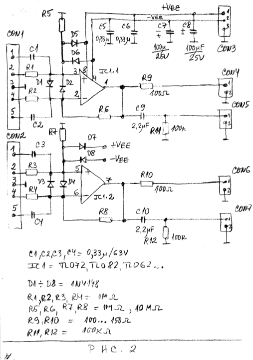
Sometimes we should capture and observe with oscilloscope differential signals. Most of the oscilloscopes need special differential probes or pre-amplifiers in order to capture these signals. Figure 2 presents the schematic diagram of the buffer with differential inputs.
The buffer is with two channels.

We can use dual operational amplifiers as TL072, TL082, TL062 or similar. The buffer is with input resistance above 1MOhm. The input resistance depends mainly on resistors R1, R2, R3 and R4. If we have R1 = R2 = R3 = R4 = 1MOhm the voltage gain is +1. If we have R1 = R2 = 1MOhm and R3 = R4=10MOhm the voltage gain is +10.
Preferably, the output of the buffers from Figure 1 and Figure 2 should be loaded with resistance higher than 10 kOhm.
The power supply
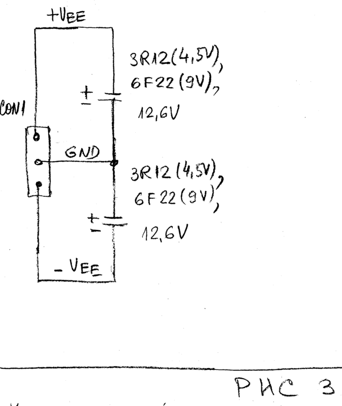
The buffers may be used in the full power supply range of the amplifiers. In most of the cases we can use +-9V from small batteries 6F22 or +-12.6V from two rechargeable batteries of 12V. Figure 3 shows how we can use dry batteries or rechargeable batteries to provide power supply for the buffers.

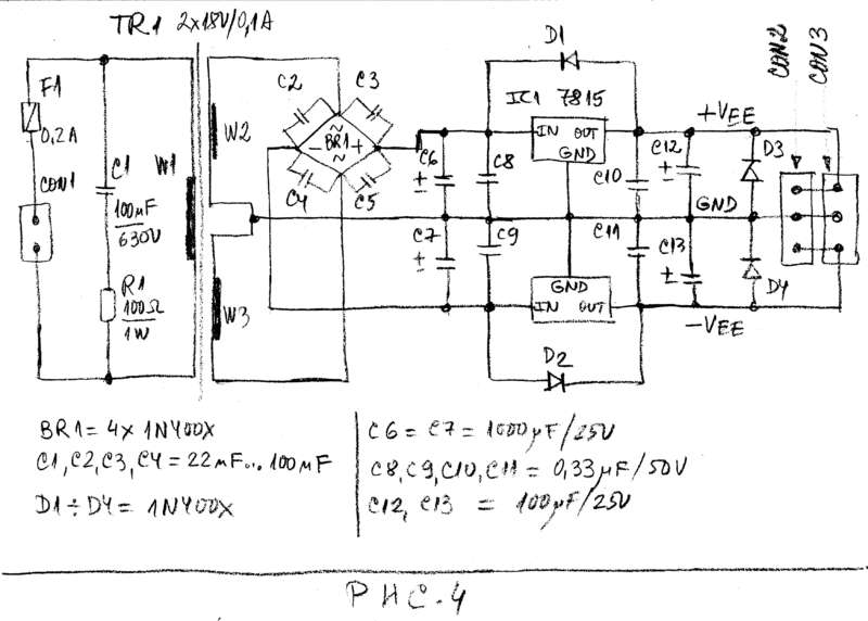
The preferred power supply should be well filtered power supply of +-15V. Figure 4 shows the circuit diagram of power supply whish can provide +-15V for the buffers.

We can use the voltage regulators 78L15+79L15 (0.1A), 78M15+79M15 (0.4A), 7815+7915 (1A) and similar.
Advantage of the proposed solutions
The proposed high impedance buffers have the following advantages:
- Low cost, low complexity;
- Low noise, low total harmonic distortions;
- Wide frequency range to more than 1MHz, depending on the op-amp.
- Wide range of applications, universal buffers
The buffer can be used as instrumentation buffer, microphone buffer, guitar buffer, etc.
- Easy to be repaired;
- Over voltage protection of the input and the outputs;
- Could be used for measurement of AC and DC voltages;
- Suitable for project of hobbyists, students and educational institutions;
Conclusion
Simple low cost AC and DC buffers for low cost and educational measurement equipment are described.
The main purposes of the buffers are:
- To increase the input resistance;
- To reduce the input capacitance;
of the low cost measurement instruments.
Also the buffers were used to protect the inputs of the measurement equipment against fault operation during the experiments. The buffers do not have offset control. That is done in order to keep the circuits the simplest possible. In case of needs the offset should be measured and taken into considerations.


