 This is a project for a voice controlled home automation system to control appliances with your voice through an Android app. An Arduino Mega board is used for controlling the relay through which an appliance is switched on/off. You can modify the Android app to add more functions.
Contents
- Voice controlled home automation system Block Diagram
- Circuit and working for the voice controlled home automation system
- Software used in the making
- Construction and testing the automation system
- Links for the required files
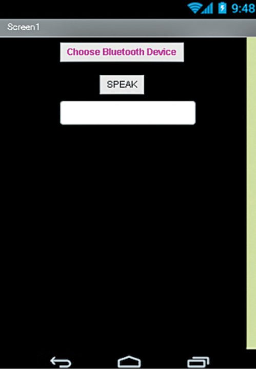
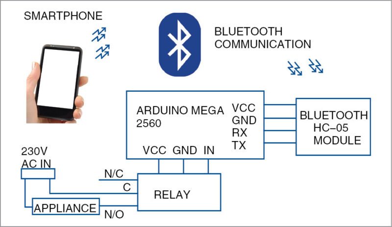
First, download Bluetalk app and install it on your Android phone. Screenshot of Bluetalk app is shown in Fig. 1. Block diagram of the voice-controlled home automation system is shown in Fig. 2.
Circuit and working of the voice controlled home automation system
Circuit diagram of the voice-controlled home automation system is shown in Fig. 3. The circuit consists of Arduino Mega 2560 board (Board1) for comparing the input string received through Bluetooth with the stored string to give output to digital pin 6 of Board1 to control the relay.

Bluetooth module HC-05 transmits and also receives data serially via Board1 that can be read by the microcontroller (MCU). A relay is used here to control only one appliance, though you can use a multichannel relay board to control multiple appliances. Mega 2560 has 54 digital pins, each of which can be used to control an appliance. The MCU can be programmed to compare the relative strings (speech).
Software
 There are two software programs used in this project. One is Arduino sketch (Bluetalk.ino) for the MCU and the other is Android app (Bluetalk.apk).
Arduino IDE is used for programming the MCU. For developing Android app, MIT App Inventor is used, as it is easier to use as compared to Android SDK. MIT App Inventor is good for hobby projects and DIY enthusiasts to create small apps for their project-specific use.
Bluetalk.apk app uses Google’s speech-recognition function and transmits the text to the MCU via the connected Bluetooth (HC-05). The .apk code can be read by importing Bluetalk.aia file in MIT App Inventor.
Both .apk and .aia files can be downloaded from the source folder present at the end of the article.
Install Arduino IDE (v1.6.9) in your PC and connect Arduino board (here, Arduino Mega is used but we can use any other Arduino board) to the PC with the help of a serial cable. Choose correct serial COM port of the board and then upload the sketch to the MCU. Disconnect the serial cable from Arduino board and connect to the relay and Bluetooth module HC-05.
Again connect Arduino board to the PC via a serial cable. An LED (not shown here) on Bluetooth module will start blinking rapidly, which means it is not connected. Once HC-05 module is connected via the smartphone, the LED will blink just twice after some delay.
Now, say something on the smartphone and check data on the serial monitor of Arduino IDE. After confirming that you are receiving data from HC-05 module, you are good to go. Make sure you select the appropriate baud rate (9600 here). Next, disconnect the serial cable and connect the relay to the appliance as shown in the circuit diagram.
Construction and testing
A single-side PCB pattern of the voice-controlled home automation circuit is shown in Fig. 4 and its component layout in Fig. 5.
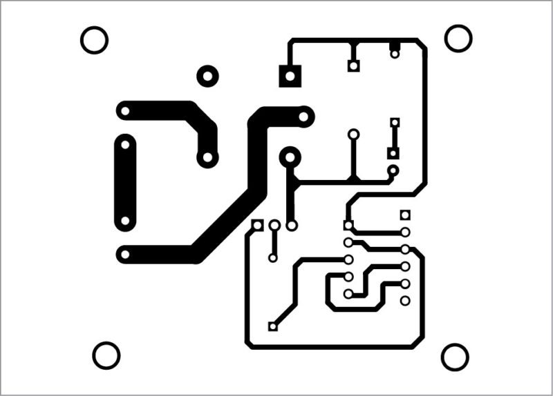
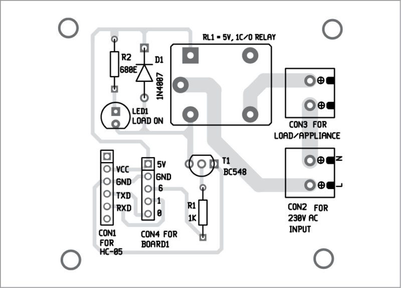
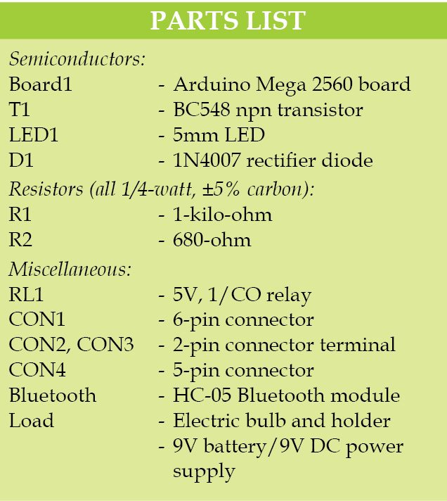
Assemble the circuit on the PCB to minimise time and assembly errors. CON1 is used to connect HC-05 module, CON2 and CON3 are 2-pin connectors used to connect 230V AC mains and load (bulb), respectively. CON4 is used to connect Arduino board (Board1).
Power on Arduino board using a 9V DC battery (or any USB 5V DC power supply) to enjoy wireless control of your home appliances via speech. Upload Bluetalk.ino sketch into Arduino board and install Bluetalk.apk on your Android phone.
- Pair your Android’s Bluetooth to HC-05 module.
- It will prompt you to enter a password.
- Default password is 1234.
- Open the app and connect to HC-05 again.
- Your voice controlled home automation system is ready to work.
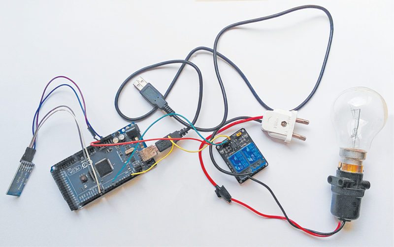
Touch ‘Speak’ icon on the app, say ‘Turn On’ in front of your smartphone to turn the appliance on and ‘Turn Off’ to turn it off. Author’s prototype is shown in Fig. 6.
Download PCB and component layout PDFs: click here
Download source folder
Madhav Shyam Lakhera is a Space science enthusiast interested in DIY projects, engineering and research.


Sir, what is the maximum distance i can use to control electrical home appliance
It will be the range of Bluetooth module HC05. It is about 50 m max.
Is the code that was posted is sufficient to run the project?? or Do we need anything more? If so.,please post the complete code of this project. Hoping that we will get the reply soon 🙂 !!
Here, all coding required is just Arduino code. No extra code is required.
Very nice project. But using Arduino MEGA for it is wasting like wasting energy. You can even use ATTiny85 for this project for single relay or ATmega328 for more relays.
What will be the the total cost to make this project for exhibition????
4000 aprox
where i can find deep details about this project. thanks
Is there any specific information you are looking for?
I need flowchart for this
Sir…ARDINO UNO is enough naa..y we need ARDINO MEGA
I not understand this
Kindly elaborate your query.
hey actually i cant understand the software part of this article regarding the mit app inventor and bluetooth part.So could you just elaborate it a bit more,actually in my project the only thing i cant do is the voice sending from the android mobile to the bluetooth module.The module gets connected to the smartphone but wgat to do after that????
sir what is cost of the project?
plz post some videos about the project..!@
What are the sketch of mcu and how can we upload that
A program written using Arduino IDE is called a sketch. This program is saved on the computer as text file with the “.ino” file extension. Here, we named the sketch as Bluetalk.ino. This sketch is first compiled and then upload to the microcontroller (MCU) on the Arduino board using Arduino IDE. For more detail on Arduino, you may visit : https://www.arduino.cc/en/Tutorial/HomePage
How to open ino file in pc
can we use ardiuno uno for this project
Yes, you can use Arduino Uno but make sure you connect R1 to digital pin 6of Arduino Uno and pins TXD and RXD of HC-05 to RX0 and TX0 pins of Arduino Uno, respectively.
Sir, How many appliances We can operate by this?
Sir how m I program in hc 05 modular and delete modular and how to connect all circuit plz help me to complete my project I got all instrument show in fig
how will the total cost?
Where I can get the program for this project??please
The source code is present at the end of the article.
is this code works on micro c???
sir do you have a demo video of this project
Sir please send this mc program
sir can we make this through arduino uno board?
sir i need this project program. how can get it sir
I am using arduino uno,HC05 and 4channel relay module, can any one plss provide me sketch code
Do it really on or off the applications or is it only a demonstration..
Sir
I want a andruino code of this project
Sir how many appliance can be accumulated by the system?
Question is not clear…
Sir May I know the estimate cost of the project ?
What type of connectors are used in this project?
Can I get a program sir?
where can i find the codes ??
You can download the Source Code at the end of the article.
how this can be applied for multy loads ? and those need to work individually
csn we do that?