Laser-guided munitions are the most widely exploited electro-optically-guided precision-strike munitions on various land based, sea based and airborne military platforms, such as main battle tanks, armoured fighting vehicles, ships, fighter aircrafts and attack helicopters. In continuation of part 1 of the article, focus in this part is on laser-guided munitions. Different aspects of this class of electro-optically-guided munitions, such as delivery concept, deployment configurations, performance parameters, international status and emerging trends, are covered in this part.
Laser-guided munitions, due to high precision, efficacy and lethality, constitute an important weapon system in the arsenal of the armed forces worldwide. These have proven their lethality and efficacy beyond any doubt during several conflicts, which include their limited use by British forces in the Falklands war in 1982, during operation Desert Storm in the Gulf War in 1991 by the coalition forces against Iraq and during Kosovo War in 1999. Laser-guided munitions were used in large numbers to great effect during Gulf and Kosovo wars. These are of great tactical importance in the contemporary battlefield scenario.

Operational basics
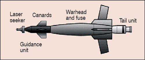
Laser-guided munitions use a type of opto-electronic position sensor subsystem known as seeker unit that determines in real-time the position of the weapon with respect to the target and feeds this information to a servo control subsystem. The servo control sub-system ensures that the weapon maintains its orientation in the desired direction of the target so as to ultimately hit it precisely. Fig. 1 shows constructional features of laser-guided munitions.
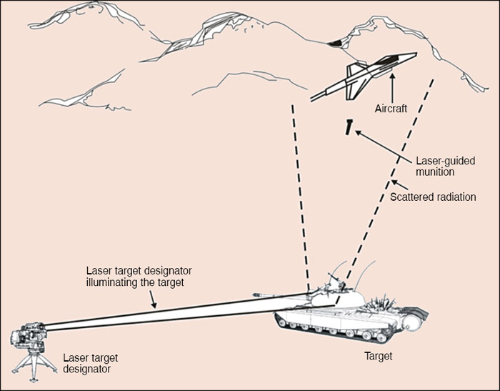
In laser-guided munitions delivery operation, the target is illuminated, called target designation, by a pulsed solid-state laser producing high peak power pulses with a known pulse repetition frequency (PRF). Peak power, pulse width and PRF are typically in the range of 5MW to 8MW, 10ns to 20ns and 5Hz to 20Hz, respectively. The laser-seeker head in the weapon makes use of laser radiation scattered from the target to generate information on the angular error, which, in turn, is used to generate command signals needed to guide the weapon to the source of scatter, which is the target (Fig. 2).
Before the weapon locks on to the radiation scattered from the target, it makes sure that the radiation is the intended one. To achieve this, the laser target designator and the laser seeker used in the guided-weapon delivery mission use the same PRF code, and the PRF code compatibility check forms the basis of identification of the desired radiation. PRF code compatibility is therefore essential to the weapon’s functionality and mission success. The code is generally chosen to an accuracy of ±1µs to ±2µs in the time interval between two successive laser pulses in a nominal value that is usually in the range of 50ms to 200ms.
The opto-electronic position sensor in the front-end of the seeker unit determines the orientation of the weapon with respect to the target. But before it does that, it deciphers the PRF of the received radiation, and only if the PRF matches with the chosen PRF value within the specified tolerance, it is further processed to extract information on the angular position of the weapon with respect to the target. Information on angular error in azimuth and elevation is fed to the servo control sub-system in the specified format, which, in turn, controls the flight trajectory of the weapon with the help of front canards and a tail unit.
The position sensor
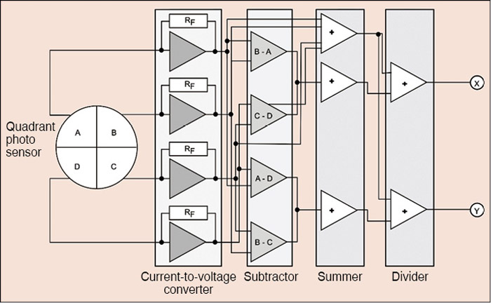
The opto-electronic sensor employed for the purpose of position sensing is usually a quadrant photo sensor. It is the heart of the laser seeker. A two-dimensional array of photo sensors is also used in some cases.


Fig. 3 explains the principle of operation of the quadrant photo sensor when used for the position-sensing application in laser-guided munitions.


