 This article presents a simple, low-cost stereo headphones buffer using two LM358 operational amplifiers (op-amps). It is used to connect the headphones to line outputs capable of driving loads up to 600-ohm.
The circuit has a high input impedance, low quiescent current and large voltage operating range. Power can be taken either from a USB or an external DC low-noise power supply. The circuit can also be connected to an MP3/MP4 player or any other audio equipment.
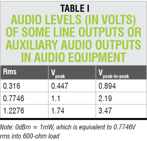
Many audio equipment, including PCs, have line output, some sort of auxiliary audio output or other low-power audio output with signals from around 0.3V rms up to around 1.3V rms (refer Table I). These outputs have sufficient amplitude to drive the headphones but usually do not have sufficient current. Outputs can drive loads having resistances around 600-ohm.
If you connect commonly-available headphones with resistance between 32-ohm and 200-ohm, it may damage these outputs. So, you need a current booster with low-impedance-driving capabilities.
Selection of the op-amp
ICs like LMV358 and LM358 are one of the most inexpensive op-amps available. LMV358 is a low-voltage, low-power op-amp working in 2.7V – 5.5V power supply range. It has very low quiescent current (typically, only 0.410mA). It is available only in SMD packages. Also, it has relatively low output current but can still be used to drive headphones. This is because many headphones require only 1mW to produce an audible sound.
LM358 is available in both classical DIP/DIL and SMD packages. It provides a lot more output current as compared to LMV358, and is also appropriate for a single power supply. LM358 has the following features:
- Output can go almost to ground with a single positive power supply.
- Output sink and source currents are typically 20mA and 40mA, respectively.
- Quiescent current is typically 3mA.
- It is suitable for battery-operated applications, including 6V, 12V and 24V batteries.
- It has gain product bandwidth of around 1MHz.
- Slew rate is typically around 1V/µs.
- Power supply range is from 3V to 32V.
These op-amps are not matched for modern operational op-amps for high-quality audio applications. However, these are suitable for IP telephony and other low-quality audio applications.
This headphones buffer can drive headphones with resistance as low as 32-ohm using 5V power supply.
Circuit and working
The circuit diagram of the configurable audio buffer for headphones is shown in Fig. 1. The circuit works with both LMV358 and LM358 op-amps. The main differences are in voltage supply range, output current, output power and quiescent currents. To drive low-impedance headphones you may need a larger current source.
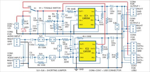
Table II gives minimal and typical output currents produced by a single op-amp and two LM358 op-amps in parallel. With these op-amps, there is enough current to drive even low-impedance headphones up to 32-ohm.
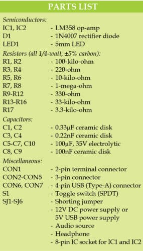
Connectors CON2 and CON3 are used for connecting audio inputs—CON3 can be used to connect with other audio equipment. Input resistance is set to 1-mega-ohm using resistors R7 and R8. This input resistance makes the circuit appropriate for many purposes, including direct connection to pickups of electrical guitars.
Outputs of this buffer are available across CON4 and CON5, which are connected in parallel. This means, the headphones can be used from CON4 and, at the same time, record music with a PC through CON5.
Buffer configurations
The configurable audio buffer has the following configurations:
- Stereo buffer with two independent channels (inputs 1 and 2): Each channel has a gain of +1. Each headphone is driven by the corresponding amplifier. Make sure to close shorting jumpers SJ1 through SJ4, while leaving SJ5 and SJ6 open.
- Mono buffer for two headphones: Right channel input is used, while left channel in not used. Buffer channel has gain of +1. The same signal is available on all outputs from the right channel. Make sure to close SJ1, SJ2 and SJ5, and open SJ3, SJ4 and SJ6.
- Mono buffer for single headphone with signal from the first right channel: In this case, all op-amps drive the same load (single headphone or loudspeaker). Make sure to close SJ1, SJ2, SJ5 and SJ6, and open SJ3 and SJ4.
- Mono buffer summing both channels in one signal and driving both headphones with the same signal (left and right): For this configuration, close SJ2, SJ4 and SJ5, and open SJ1, SJ3 and SJ6.

Construction and testing
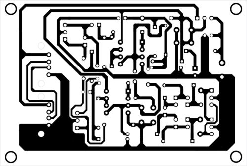
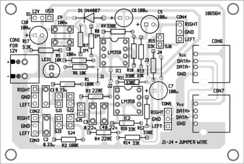
A PCB layout of the configurable audio buffer for headphones is shown in Fig. 2 and its components layout in Fig. 3. After assembling the circuit on the PCB, enclose it in a suitable box.
Download PCB and Component Layout PDFs: click here
The exact power supply of the amplifier depends on the selected load impedance of the headphones, required output power and acceptable level of total harmonic distortion (THD). The most important limitation is to not overheat the op-amps.
Power supply of the circuit can be applied on CON1, or any USB connector (CON6 or CON7). Both USB connectors are in parallel, so if you use the first one, you can still use the second to connect most USB devices.
Equalisation resistors R9 through R12 can be from 15-ohm to around 39-ohm, depending on loads, power supply and op-amps.
Petre Tzv Petrov was a researcher and assistant professor in Technical University of Sofia, Bulgaria and expert-lecturer in OFPPT (Casablanca), Kingdom of Morocco. Now, he is working as an electronics engineer in the private sector in Bulgaria.



Can a 32 ohms headphone be used on desktop front/rear line out socket directly without any amplifier?