 This Multi-Utility Protection System project is used for fire detection and then sending an SMS alert to a cellphone. The design is based on Arduino Uno. The project also includes an LCD and an LED for visual indications, and a buzzer for audio indication. It has sensory systems including flame and temperature sensors along with a relay switching device.
Agricultural equipment include farm robots, pest controls, and crops and seeds monitoring systems. This circuit generates an alarm if a fire breaks out near motors, transformers or other equipment installed in the field. At the same time, electrical load is automatically switched off. This circuit should be installed near the equipment to be monitored.
Circuit and working
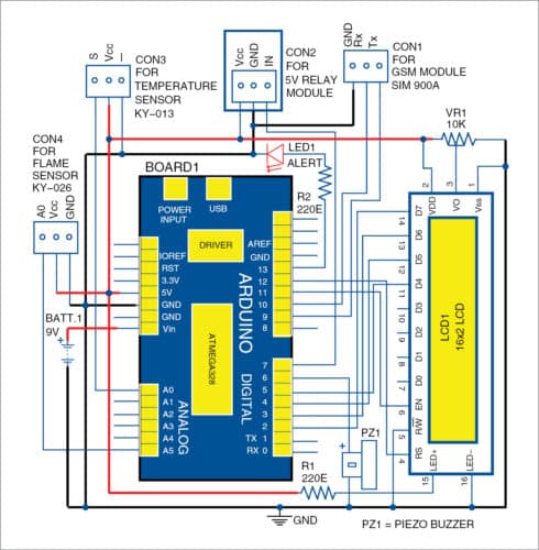
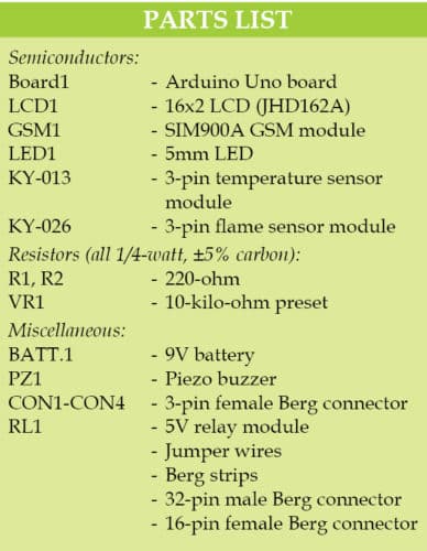
The circuit diagram of the multi-utility protection system for agricultural equipment is shown in Fig. 1. It comprises LCD (JHD162A), Arduino Uno, piezo buzzer, SIM900A GSM module, preset (10-kilo-ohm), LED, 9V battery, flame sensor, temperature sensor, 5V relay module and a few other components.

If a fire breaks out, or excessive heat or burning flame is detected near the equipment, the system generates an alert with visual LED indication and a sound alarm. Status of the environment in real time, including temperature and flame level, is displayed on the LCD.
The LCD is used to track the temperature sensor level. If the level goes beyond safe limit, immediate action can be taken. Most of the time, workers are in the field, so they can check various sensor levels through the LCD.
GSM-based SMS alert facility is also included. It allows getting the SMS alert on a cellphone at home, even at night in case of fire. The owner can then alert the worker or incharge present in the field to take appropriate action.
Flame sensor
KY-026 flame sensor module is used here. This flame detection sensor module is quite sensitive to flame or light. Detection angle can be around 30 to 60 degrees. The module operates on 5V DC. Its analogue output pin A0 is connected to pin A5 of Arduino board.
LCD module
The 16-pin JHD162A LCD module used here can display 16 characters in two lines. It is used to display the temperature level on the first line and flame level on the second.
Arduino Uno
Arduino Uno is based on ATmega328 series microcontroller (MCU). It contains 14 digital input/output pins (of which six can be used as PWM outputs), six analogue inputs, 16MHz crystal oscillator, USB connection, power jack, ICSP header and reset button.
GSM module
GSM SIM900A module works on frequencies from 900MHz to 1800MHz. It includes RS232 interface, which allows connecting the PC and MCU with RS232 chip. Baud rate can be set in the range of 9600 to 115200. It contains internal TCP/IP stack to enable connection with the Internet via GPRS. It is suitable for SMSes, calls and Internet connectivity applications.
Temperature sensor
NTC thermistor-based KY-013 sensor module is used here. It is an analogue temperature sensor module compatible with Arduino. A thermistor is a low-cost, small device. It is sensitive to ambient temperature variation. It is used to detect the temperature of the surrounding environment. KY-013 can be directly connected to analogue pin A0 of Arduino to detect temperature changes in the environment. The temperature measuring range is between 20°C and 80°C.
Preset
A preset is a three-terminal resistor with a rotating contact that makes an adjustable voltage divider. If only two terminals are utilised—one end and the wiper—it behaves like a variable resistor or rheostat. A 10-kilo-ohm preset (VR1) is used here.
Software
Programming of the project is done on Arduino IDE version 1.8.6. Pin A5 of Arduino for the flame sensor and pin A0 of Arduino for the temperature sensor are defined in Arduino program code/sketch (agriculture.ino). The program displays flame and temperature levels on the serial monitor in the PC and on the LCD in digital form.
Download Source folder: click here
Construction and testing
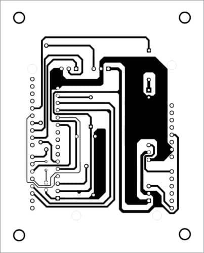
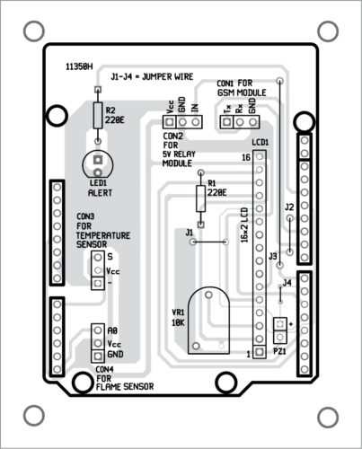
The PCB layout of the multi-utility protection system is shown in Fig. 2 and its components layout in Fig. 3.


Download PCB and Component Layout PDFs: click here
Assemble the components on the PCB. Make connections as per the circuit diagram. Note that 32-pin male Berg connectors should be connected on the PCB from solder side and should be soldered on the components side. Then, insert this board into the 32-pin female Berg connectors on top of the Arduino board.
Switch on the power supply by connecting 9V battery to the circuit. Check flame level on the LCD and the serial monitor. If there is a burning flame or sparks in motors, transformers or other devices, the circuit will send a buzzer alert, update the status of flame and temperature levels on the LCD, cut off the load by de-energing the relay, and the system will send an SMS to the registered cellphone.

For initial testing, light a candle and bring its flame near the flame sensor. Monitor the flame detection distance against the flame values shown on the serial monitor. Sensitivity can be adjusted using inbuilt potentiometer in KY-026 module.
On pressing S on the serial monitor, the system starts recording the flame intensity level. If the value goes beyond the threshold level, the buzzer sounds an alarm and LED1 starts blinking. At the same time, it sends an SMS alert to the cell number included in the software code. The flame level can also be viewed on the serial monitor and the LCD.
Test the circuit in various situations and make sure it is working well before use.
Navpreet Singh Tung is assistant professor and project coordinator, Department of Electrical Engineering Bhutta Group of Colleges, Punjab.


Sir can you upload the source code for this??.the link for the source code is unavailable.
Hi Arvind, the source code is present at the end of the article. You can also download the Source code is here.