 The aim of this project is to develop a 4-channel wireless remote control (RC) system with one XBee each in transmitter and receiver.
This is a remote-controlled aircraft project based on Arduino and XBee modules. The aircraft’s movement is controlled through a brushless DC motor and three servo motors. It has an XBee-based remote control at the transmitter end and an Arduino-based aircraft at the receiver end. The aim of this project is to develop a 4-channel wireless remote control (RC) system with one XBee each in transmitter and receiver.
Circuit and working
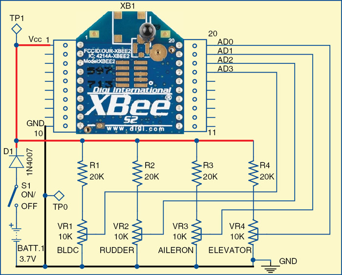
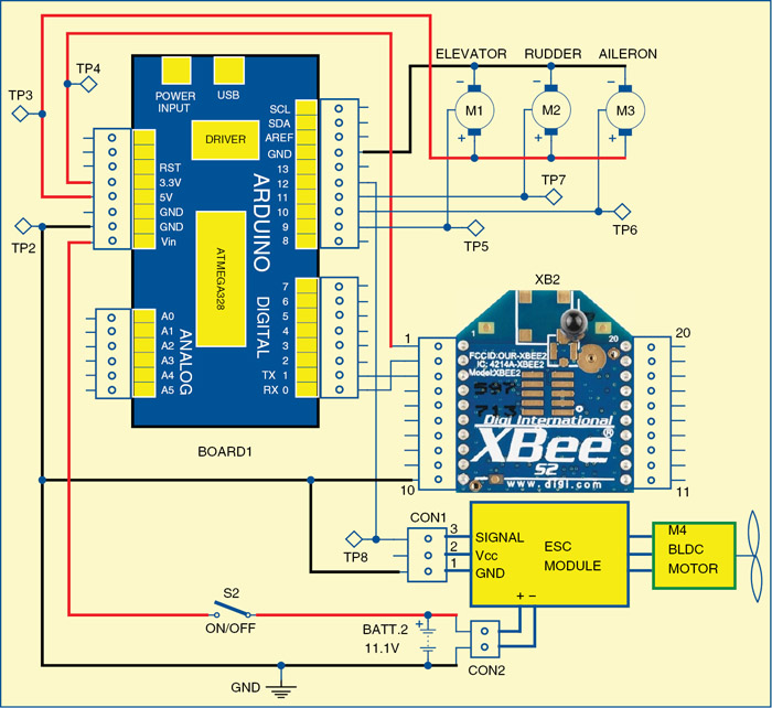
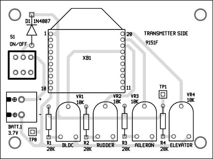
Fig. 1 shows the circuit of XBee-controlled aircraft transmitter section and Fig. 2 shows its receiver section. The circuits are built around Arduino UNO (board1), a pair of XBee module (XB1 and XB2), electronic speed controller (ESC) module, three servo motors (M1-M3) and a BLDC motor (M4).

Transmitter section is driven by a 3.7V battery and receiver section by an 11.1V LiPo battery. 11.1V is used to power the brushless DC motor (or BLDC motor) through ESC module. The Arduino board1 receives power supply from 11.1V battery at its Vin input pin.
The four potentiometers in transmitter section are used for sending different control signals to the receiver section through RF modules. Control signals received in the receiver are processed by microcontroller in the Arduino, which in turn controls a BLDC motor and the servo motors for rudder, aileron and elevator of the aircraft.
Arduino Uno board
Arduino is an open source electronics prototyping platform based on flexible, easy-to-use hardware and software. It is intended for artists, designers, hobbyists and anyone interested in creating interactive objects or environments.
Arduino Uno is a board based on ATmega328 microcontroller. It consists of 14 digital input/output pins, six analogue inputs, a USB connection for programming the on-board microcontroller, power jack, an ICSP header and a reset button. It is operated with a 16MHz crystal oscillator and contains everything needed to support the microcontroller. It is very easy to use as the user simply needs to connect it to a computer with a USB cable or power it with an AC-to-DC adaptor or battery to get started. The microcontroller on the board is programmed using Arduino programming language and Arduino development environment.
XBee module
XBee is a small 2.4GHz transceiver with a small microcontroller on board. It is a communication protocol which is used in many other instruments too.
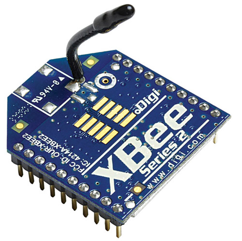
There are two types of XBee radio transceivers: series 1 and series 2. Each series has two varieties: normal and pro. While the normal has a range of 30 to 40 metres in indoor or urban situations, along the line of sight it works up to 100 or even 125 metres. The pro is effective up to 1.6km on line of sight. However, with a Yagi directional antenna, XBee pro can reach as long as 20km on line of sight.
While series 1 has eight digital I/O pins, series 2 has 11 pins. Series 2 is more advanced and can be made into mesh networks whose range can be extended to any length by putting router XBees in between.
Analogue input and XBee
XBee analogue input pins read 0V to 1.2V maximum. Any voltage above 1.2V is treated as maximum or 1. Since most XBees operate at 3.3V, we reduce this voltage to 1.2V by adding a suitable resistor along the input device.
Suppose the analogue sensor is an LDR whose impedance varies from 0 to 10k, to drop 3.3V to 1.2V across the LDR we put a 20k resistor in series with the LDR, so that two-third voltage (of 3.3V) is dropped before reaching the LDR.
Transmitter side
Pins 20 through 17 of XB1 are connected to four 10k presets (VR1 through VR4), which are used to control BLDC motor (refer Fig. 4), rudder, aileron and elevator, respectively.
Receiver side
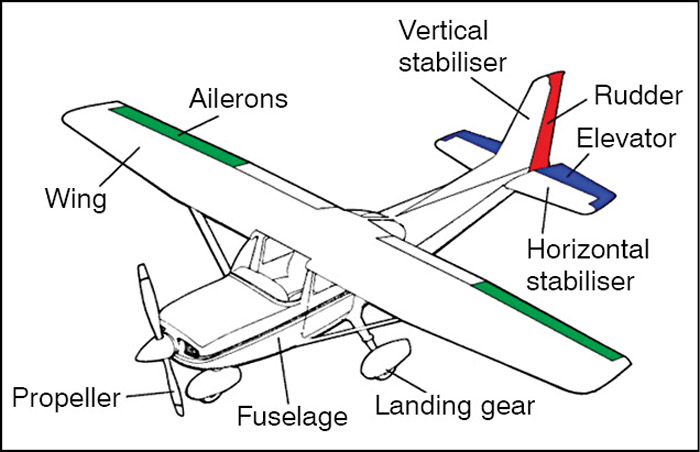
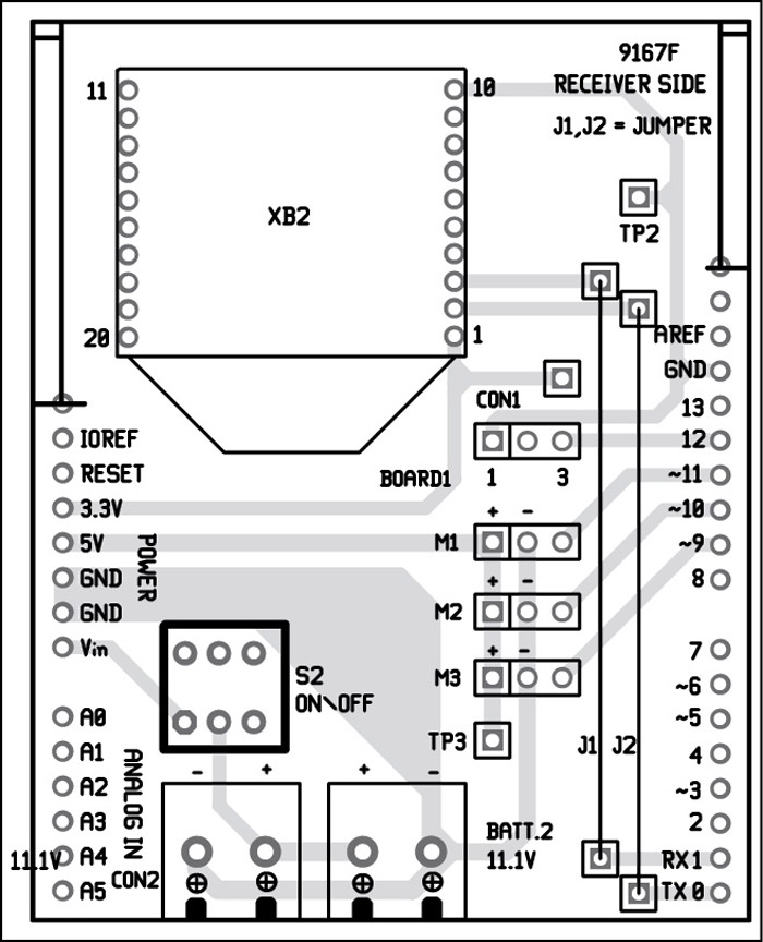
Pins 0 and 1 of board1 are connected to pin 2 and 3 of XB2. Pins 9, 11, 10 and 12 of the board are connected to signal pins of M1 (elevator), M2 (rudder), M3 (aileron) servo motors and ESC module (refer Fig. 5), respectively. Main body parts of a typical RC aircraft are shown in Fig. 6.
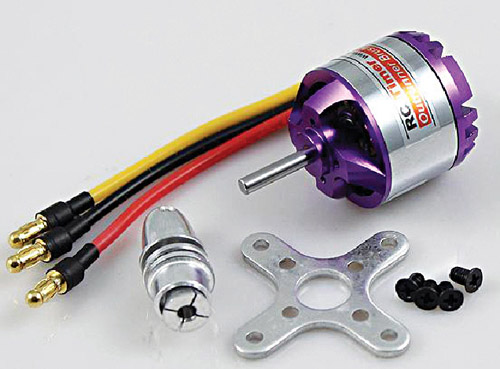
BLDC motor is used for propeller of the aircraft. The propeller, or airscrew, converts rotary motion from motor to provide propulsive force. It is the most important part of the aircraft. The propeller is mounted on the front side of the aircraft and is generally made of two or more blades.
A rudder is used to steer the aircraft when it moves through the air, controlling the direction in which the aircraft is pointing. It is a flat sheet of material attached with hinges to the craft’s stern, tail, or after end.
An aileron is a hinged flight control surface, usually attached to the trailing edge of each wing of an aircraft. Ailerons are used in pairs to control the aircraft in roll, or movement around the aircraft’s longitudinal axis.
Elevators are flight control surfaces, usually at the rear end of an aircraft, which control the aircraft’s longitudinal altitude. The position of the elevator controls whether the nose of the airplane is pointing up or down, and accordingly the plane moves up or down. The elevators are usually hinged to a fixed or adjustable rear surface.
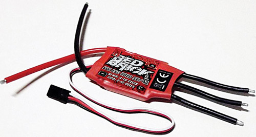
Input supply wire of ESC is connected to 11.1V battery. Three output wires of ESC are connected to three-phase inputs of BLDC motor (M4).
Software
Arduino UNO is programmed using Arduino IDE software. ATmega328 on Arduino UNO comes with a boot loader that allows you to upload new code to it without the use of an external hardware programmer. It communicates using the STK500 protocol.
You can bypass the boot loader and program the microcontroller through in-circuit serial programming (ICSP) header, but using boot loader programming is quick and easy. Select the correct board from ‘Tools -> Board’ menu in Arduino IDE 0022 and burn the program (sketch) through standard USB port in the computer.
We used Red Brick ESC module. If you use any other ESC module, you may have to modify delays in the code accordingly.
Programming an XBee
Several communication programs are available for programming an XBee, such as procontrol, xterm, pcu, X-CTU, even putty, but among these X-CTU is the easiest, Windows-based graphical program, though it takes longer time. But once you master X-CTU, you can quickly connect XBee to any other communication program and do the reprogramming of your XBee through short AT commands.
Download X-CTU from the Internet and install it on a Windows PC. Position the XBee on the Explorer board and connect it to the USB port of your PC. Fire up X-CTU and see whether it detects the device or not.
The two XBees can be made to communicate with each other freely and precisely through X-CTU software. The X-CTU has four tabbed windows: PC settings, Range test, Modem and Configuration. In PC settings window there are three sub-windows located at the bottom: Host setup, User com ports and Network Interface. In case you have not found your right com ports, you can click Network Interface and then Digi Device Discovery to find your device.
Press Test/Query button on right side of the same PC Settings window and see what XBee it discovers. Check Enable API box because we will use this feature in Coordinator Xbee (XB1). Now come to Configuration window where most of the settings need to be made.
In Configuration window, click on Read button and your screen will start showing lots of data. Do not get alarmed; you need to configure only a few parameters.
Click on Always Update Firmware, as this will keep the XBee updated with the latest software. In Function Set pull-down menu select XBee Coordinator API. In Version pull-down select the highest number. In Networking parameters window find the personal area network (PAN) parameter, and give it a 4-digit number, say, 7821. Do not give 1234 because most people use this number. In case another person is experimenting with XBee in your area, you both will collide in the air space for bandwidth.
For communication between two XBees, one has to be made Coordinator and the other a Router. Here we are preparing the Coordinator XBee (XB1).
Coming to the Addressing parameter at DH and DL, these are called the High and Low addresses. DH is a 32-bit address written on the XBee itself. Enter this parameter here. In most cases, it is the same number for all generic XBees: 0013A200 (find out yours to be sure). Just below this number you will find another 32-bit number inscribed on the XBee. This is the DL number.
The DL parameter is to be switched between the Coordinator and the Router; the Router number to be entered into the Coordinator and vice versa. After doing that check Write and the setup will be written in your Coordinator XBee. See the message below. You may need your Internet connection on now. When it is over, ‘finished’ message will appear at the bottom.
Pat yours back; you have set up the XBee Coordinator successfully! Now remove the Coordinator and insert the other XBee (XB2) and open Configuration window. After checking Read, and getting the parameters shown on the middle window, go to the Function Set pull-down menu and select XBee Router API. In Version pull-down select the highest number. Find the PAN in the Networking parameter and enter 7821 (same as the Coordinator XBee). Set the JV parameter as 1, as it will set the Router to rejoin the coordinator on startup.
Download PCB pattern and component layout PDFs: click here
Download source code: click here
In Addressing parameter the DH shall be as written on the XBee and the DL shall be the DL number written on the Coordinator XBee. So far so good! Now come down further to IO Settings to set up analogue and digital data entry part of the router XBee.
In the IO Settings parameter, D0, D1, D2, D3 are the four analogue input pins through which we will send our 4-channel analogue data. By default these pins are disabled. To enable them, go to IO Settings and make D0, D1, D2, D3 as 2 (as analogue data entry). However, these pins can be made digital data input or output pins also by simply changing to 3, 4 or 5. Set D5 to 4. This pin will be used as feedback signal from receiver XBee (XB2).
Now come to I/O Sampling section and set the IR sampling to 64, that is, 0X64. Once it is on 100-millisecond the feedback will be checked.
Check Write and let the configuration be written in XBee (XB2).
Construction and testing
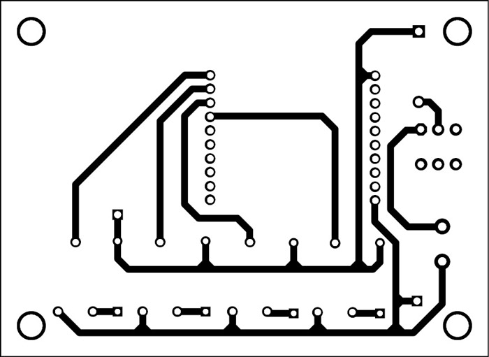
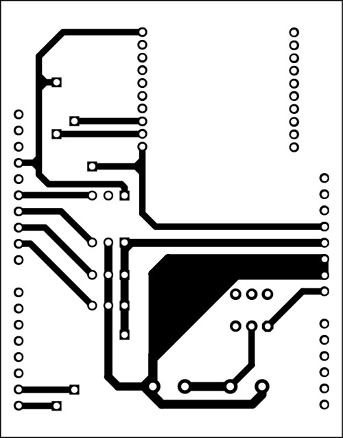
An actual size, single-side PCB for the XBee-controlled aircraft transmitter circuit is shown in Fig. 7 its component layouts in Fig. 8. PCB for receiver circuit is shown in Fig. 9 and its component layout in Fig. 10.
PCB of receiver board1 is in the form of shield, so mount it on top of Arduino UNO board. Connect 3.7V battery to transmitter section and 11.1V battery to receiver section. Check working of BLDC motor by varying VR1, of servo motor M1 using VR4, of servo motor M2 using VR2 and of servo motor M3 using VR3. If there is any problem, verify voltages at test points given in the table.
Building an RC aircraft requires some basic skills and creativity. There are rich tutorials available on the Internet. Some useful information to build your own RC aircraft can be found from the links below:
http://www.easyrc.com/airplanes/
http://rcvehicles.about.com/od/diyaircraft/
http://www.stenulson.net/rcflight/rcflight.htm
You can either build the body of the aircraft yourself or get it ready-made from an electronics spares shop. The receiver PCB, along with the 11.1V battery, should be mounted firmly in the aircraft.
The RC aircraft can be launched by gathering speed on a long runway while some are launched by hand by literally throwing them into the air. In the first case, as soon as your plane builds up enough speed and catches wind, it will lift from the ground. But note that, if the runway surface is uneven (like grass-covered), your plane might not be able to gather the necessary speed for take-off. In that case you should opt for hand-launch.
Remember, the aircraft is controlled by a remote control which has a finite range. If your plane gets too far away from you (either vertically or horizontally), you might lose control and the plane would plummet back to the ground. The usual way to fly it is in circles above your head.
After assembling the complete project, switch on transmitter and receiver circuits. Slowly vary VR1 to increase the speed of the BLDC motor (propeller). Once the plane takes off and is stabilised above the ground, vary VR2, VR3 and VR4 one by one, gradually, and observe the effect on flight pattern. To return plane back to ground, reduce its speed using VR1.
The author is an avid user of open source software. Professionally, he is a thermal power expert and works as additional general manager at NTPC


