Test instruments are used to make measurements. These are required in production units, R&D laboratories, calibration laboratories, maintenance and service centres, etc. For qualifying any prod-uct or subsystem of a product (such as amplifier,oscillator and transmitter) that comes out of a production unit, measurements are to be performed to findout whether the product meets the required specifications. After making measurements, one can declare that the units are working as per the given specificationsand are ready for delivery. In R&D laboratories, instruments are needed to verify whether the developed module is behaving as per the design specifications.
You should judiciously select test instruments considering your present as well as future measurement requirements. As test instruments are usually very expensive, proper care should be taken to select one that provides you the best value for your investment. To help you out, here we discuss the basic criteria for selecting the right RF measuring instrument for your needs.
General considerations
The most important and essential factor in selecting test instruments is their reliability. They should function within the given specificationsat any time, in any place and over a long period. An unreliable instrument will give unreliable results, which is obviously not desired. Hence you should purchase these instruments from reputed vendors. The catalogue of the vendor should be studied for their selection of components, development and manufacturing stages. Vendors can be asked to supply the users’ feedback on the performance of instruments.
The second important factor is the accuracy of the measurement claimed by the manufacturer. Accuracy is the closeness of the measured value to the true value. Since measuring instruments are mother tools, these should provide a high measurement accuracy. So ascertain the company’s traceability to national standards.
The third factor is after-sales and support facilities provided by the company. Even if the product is highly reliable, there is some component of unreliability associated with it. As per Murphy’s Law, the instrument may fail at a crucial time. To reduce the downtime due to instrument failure, repair time is to be minimised. Prompt service by the company will naturally reduce the repair time. Hence the company should have a wide network of sales and service offices. The service office should be nearer to your location. For example, if the service centre is far away from your location, downtime will be more, affecting the production schedule. For the same reason, if the instrument is procured from abroad, the manufacturer should have service centres in India.
Technical considerations
Before purchasing an instrument, you should know what purpose the instrument is being purchased for and then generate specificationsof the instrument. Specificationsshould take care of the current requirements as well as the possible future requirements to some extent. Over-specificationswill unnecessarily increase the cost of the instrument.
For example, if an RF equipment manufacturer wants to purchase some test instrument, the instrument should cover all the frequency ranges in which the manufacturer is involved. The life of any test instrument is approximately 15 years. Beyond that period, the instrument will become obsolete and repair will not be economical. If you plan to increase the frequency range of your products in the next five years it is better to include those frequencies now itself instead of purchasing additional instruments after fiveyears. If there are no plans of expansion, the current requirements alone should be the deciding factor while specifying the instruments. Alternatively, you can go for instruments that can be augmented easily for future requirements by installing plug-in modules. Additional plug-ins can be procured when the actual requirement of a higher frequency range arises. This will reduce the investment cost.
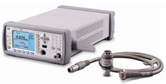
An example is RF power meters with different power sensors or detectors. You can select a power sensor covering the required frequency range and, when the need arises for extra frequency ranges, different power sensor can be procured keeping the same basic power meter.
Sometimes one single instrument can do the job of many instruments. For example, level generator, frequency counter and power meter are combined and available as a single instrument. Cost-wise this is cheaper than purchasing three separate instruments. This is advantageous for small establishments where working manpower and space are limited. In mobile systems like mobile transmitters, such instruments are recommended as space is the limiting factor along with cost minimisation. The disadvantage, of course, is that the use of one instrument will block the use of other two instruments. A single failure can affect the entire measurements. So depending on your requirement, select a combined instrument or separate instruments.
Major specifications
Range. While ordering a test instrument, you should specify the required measuring range of the instrument. For example, if it is a multimeter, specify the maximum to minimum values of the voltages, current and resistance to be measured. For instruments that are frequency-sensitive, the frequency range of operation should be specified.For frequency counters, the minimum to maximum frequency to be measured should be specified The requirement may be from a few hertz to a few gigahertz depending on the application.
In some cases, both frequency and amplitude ranges have to be specified Signal generators and frequency synthesisers are such types, and one has to specify the output frequency range and maximum power output levels. Power meter is another such instrument where one has to specify the range of frequencies for which power has to be measured and the range of power level to be measured. The measurement range needed may be from a few microwatts to a few watts. The ranges may be covered with different power sensors.
Accuracy. Typically, the term ‘accuracy’ in measurements refers to the closeness of a measurement result to the true value. The cost of the instrument increases with increase in its accuracy level.
The requirement of accuracy level depends upon the nature of measurement. For example, laboratories engaged in calibration and issuing certifiates need highly accurate instruments. A company that makes consumer articles need not have very accurate instruments.
Let’s consider another company that supplies crystal oscillators having stability of the order of 1E-7/day. Naturally, the counter used by the company should be at least ten times more stable than this. The measurement accuracy of the frequency counter depends upon the stability of the crystal oscillator used as reference for time-base generation in the counter.
It may use an oven-controlled crystal oscillator or temperature-compensated crystal oscillator. Counters having stability of 2E-8/day to 5E-10/day are available and you can select a particular one depending upon the purpose of measurement. Basic counters have a low order of stability but offer options for higher-order stability. One has to mention the option in case a higher stability is required. For example, if the crystal stability is 1E-7/day, with option 01 it may be 1E-9/ day. So while ordering a higher stability, specify the option number.
Sensitivity. This gives the minimum required signal for an instrument to function. It is definedfor instruments that accept signal for making measurements. Frequency counters, power meters, voltmeters and spectrum analysers are such types of instruments.
In the case of a spectrum analyser, sensitivity is a measure of the ability to detect and display a small signal, and it is equal to the noise generated by the instrument itself. A signal level equal to the noise level will give a 3dB display. Signal levels less than the sen-sitivity cannot be detected.
Sensitivity of spectrum analysers depends on the resolution bandwidth. Sensitivity at 10kHz resolution band-width will be 10 dB better than sensitivity at 100kHz resolution bandwidth. So while definingsensitivity of spectrum analysers, resolution bandwidth is also to be specified.
Sensitivity of spectrum analysers is also called ‘displayed average noise level.’ It can be increased with the use of an additional preamplifiersupplied by the manufacturer. The preamplifie will have a very low noise figurecompared to the spectrum analyser, thus increasing sensitivity.
In the case of frequency counters, sensitivity is the minimum signal level at which the counter can read the frequency. For signals below this level, the counter will not respond.
For oscilloscopes, sensitivity is define in terms of defection factor. Vertical volts/division gives sensitivity.
In the case of power meters, sensitivity is the minimum power level that can be measured. A power meter consists of a power sensor, which is connected to the power meter through a cable. The frequency range of measurement and sensitivity depend on the power sensor used. A single sensor may not cover the entire range of frequencies as well as power levels. For higher power-level measurements and very low power-level measurements, separate sensors may be required to cover the power-level range. The cost of the power sensor may be high. So select a power sensor depending upon your application requirements. Future requirements can be met by procuring an extra power sensor whenever the requirement arises.
Maximum input. This specificationis needed for instruments that accept signals for making measurements. For power meters, the maximum input is the signal power level that can be fed to the power sensor without damaging the sensor. If signal level beyond maximum input is fed, the sensor may get permanently damaged. In spectrum analysers, the maximum input signal is the level that will not damage the firstmixer of the spectrum analyser. Signal level beyond it will damage the firstmixer permanently and sensitivity of the spectrum analyser will be poor.
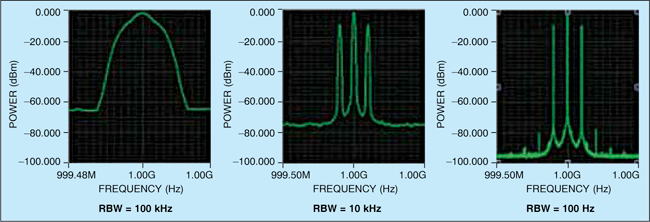
Resolution. This is the ability to resolve the two values being measured as two different and distinct values. For example, in the case of spectrum analysers, two signals separated by a given frequency should appear as two different signals. This will happen only if frequency separation is more than resolution bandwidth (RBW) of the spectrum analyser. If frequency separation is less than resolution bandwidth, the two signals will merge and appear as a single signal.
Fig. 1 shows displays with different RBW settings. In the first display, RB is 100 kHz and the sideband signals have merged to appear as a single signal. In the second display RBW is 10 kHz, and in the third display RBW is 100 Hz. Here the sidebands are clearly separated and resolved as different frequency components.
Thus for spectrum analysers, frequency resolution is to be specifiedin order to resolve different frequency components.
In the case of frequency generators, resolution is the ability to set the frequencies that are distinguishable. This is the smallest increment by which the output frequency can be changed.
Frequency resolution is an important parameter for frequency synthesisers. Frequency synthesisers are basically variable-frequency generators that are very accurately and quickly settable and highly stable. The output frequency can be varied in steps—the smallest step being the resolution.
Frequency synthesisers are used as the reference source for phase-locked oscillators. The output of phase-locked oscillators will be some integral multiple of the reference source. For example, if the multiplying factor is 50 and the phase-locked oscillator frequency is to be changed in steps of 1000 Hz, the synthesiser should have a resolution of at least 20 Hz. Thus the resolution specification depends on th requirement.
In the case of instruments that measure power levels, resolution is the ability to distinguish two power levels. If resolution is 0.1 dB, power levels separated by less than 0.1 dB cannot be distinguished. In case, the stability of power amplifers is 0.2 dB/day, to measure it, the power meter should have a resolution higher than 0.2 dB.
Other specifications
Rise time. Some specificationsare relevant to a particular type of measuring instruments. For example, rise time is relevant to oscilloscopes. For pulse waveform measurements, rise-time specificationis very important. It is defined as the time taken to reach fro 10 per cent to 90 per cent of the maximum value. Rise time depends on the bandwidth of the oscilloscope:
Rise time (in nanoseconds)=350/Bandwidth (in megahertz)
A 100MHz oscilloscope will have a rise time of 3.5 nanoseconds. For analysing fast-rising waveforms, oscilloscopes should have a fast rise time. The measured rise time, the oscilloscope rise time and the actual rise time are related by:
tmeasured= √t2osc+t2waveform
Thus for minimal measurement error, the oscilloscope rise time should be small compared to that of the waveform.
FM noise. This specification is important for frequency synthesisers. Phase-locked oscillators are used for carrier generators in communication links. Synthesisers are used as the reference source for phase-locked oscillators. If multiplication factor is ‘N,’ FM noise after multiplication will increase by 20 log N. In higher FM noise, carriers may overlap with adjacent channels. Also, in narrowband communications, this will affect signal detection.
Hence FM noise in a frequency synthesiser should be properly specified. It is specified as single-sideand phase noise and given as X dBc/Hz at Y Hz away from the carrier. This means the phase noise is X dB below the carrier frequency at Y Hz away from the carrier frequency in a measurement bandwidth of 1 Hz.
In spectrum analysers also, phase noise is important as it determines purity of the measured signal. Also, unequal signals cannot be resolved as low-level signals will merge with the noise.
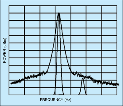
In Fig. 2, because of high FM noise, noise level close to the carrier is very high, masking the low-level signal. Thus noise sidebands affect the resolution of low signals close to the carrier.
General specifications. General specificationsare common to all types of instruments. For example, GPIB/RS-232 interface is needed to connect the instrument with a PC for control and status monitoring. The instruments can be controlled remotely through the PC and all the front-panel readings monitored on the PC. Power source specifcation and environmental specificationslike operating temperature and relative humidity are also common to all instruments.
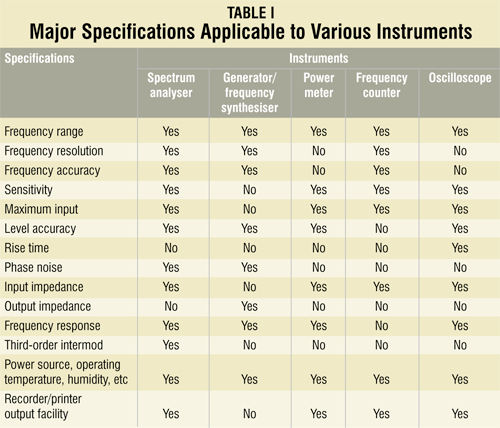
Table I shows major specificationsthat are applicable to various measuring instruments. ‘Yes’ means the particular specifiation is applicable for the instrument and ‘No’ means the specification is not applicable
In oscilloscopes, where CRT readout is available, frequency resolution may be specified. In instruments lik spectrum analysers, power meters, frequency counters and oscilloscopes, where signal is fed to the instrument, input impedance is specified Whereas in instruments like generators/frequency synthesisers, where output is taken, output impedance is specified.
Apart from the above specifcations, some specificationsfor quick checking of the instruments should be specifed. For example, in power meters and oscilloscopes, CAL out is available for checking the instrument. In signal generators, there may be requirement for amplitude modulation (AM), frequency modulation (FM), etc. For voltage standing-wave ratio (VSWR) measurements in transmission lines using slotted line, squarewave modulation is needed. These specificationsare required in synthesised frequency generators.
Thus the various specifications should be carefully selected depending upon the measurements required.
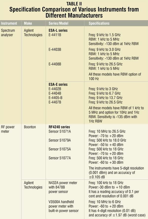
Table II shows the specificatio comparison of various instruments from different manufacturers. For example, spectrum analysers of Agilent Technology—models ESA-L series and ESA-E series—are compared. In ESA-L series, three models are shown, which cover different frequency ranges. All models have almost the same sensitivity and resolution bandwidths. Optional lower-resolution bandwidths are also available. In ESA-E series four models are shown, which cover different frequency ranges. All have the same sensitivity and resolution band-width specifications. Optional 1Hz resolution bandwidth is also available. So one has to select a model depending on the frequency of operation and resolution bandwidth requirements.
Another example shown is RF power meter. Power meter from Boonton Electronics Corporation covers different frequency ranges and different power level ranges with different models of power sensors. One has to select a particular sensor depending on frequency range and power measurement range.
Agilent Technologies has a power meter with power sensor covering up to 18 GHz and power range from 1 microwatt to 10 milliwatts. Another meter is a portable handheld model with built-in power sensor covering up to 6 GHz and power range from 1 nanowatt to 100 milliwatts. This also operates on battery. It is suitable for transportable installations where space is a constraint. All power meters have a resolution of 0.001 dB. You can select a power meter that meets frequency and power range requirements of your application.
For example, for a satellite communication earth station operating in C-band frequencies, frequency range up to 6 GHz is sufficient.For stations operating in Ku-band frequencies, frequency range up to 14 GHz is required.
To sum up
While selecting a test instrument, keep in mind present as well as near-future requirements. Accordingly, generate specifications.Compare these specificationswith the specificationsof instruments available from reputed vendors and narrow down your choices by selecting instruments that meet the required specifications. Now fro these options you can select one that costs the least.
The author has retired from ISRO as a scientist/engineer


