 With limited fossil fuel reserves for the next few years and the problem of pollution that they cause, renewable energy is the need of the hour to tackle these issues. Solar power is one of the best options for this.
But maintaining a solar power plant for energy generation is currently difficult as they contain several solar cell units. Looking after each and every one so that they produce energy with the highest efficiency is difficult.
The issue can be resolved if the power production of each solar panel is obtained wirelessly. This can help in estimating the solar plant’s overall power production using power generation analytics, thus allowing to monitor them individually based on their power generation scale. Any faulty device or panel can also be timely cleaned and repaired to maintain its consistent power generation efficiency.
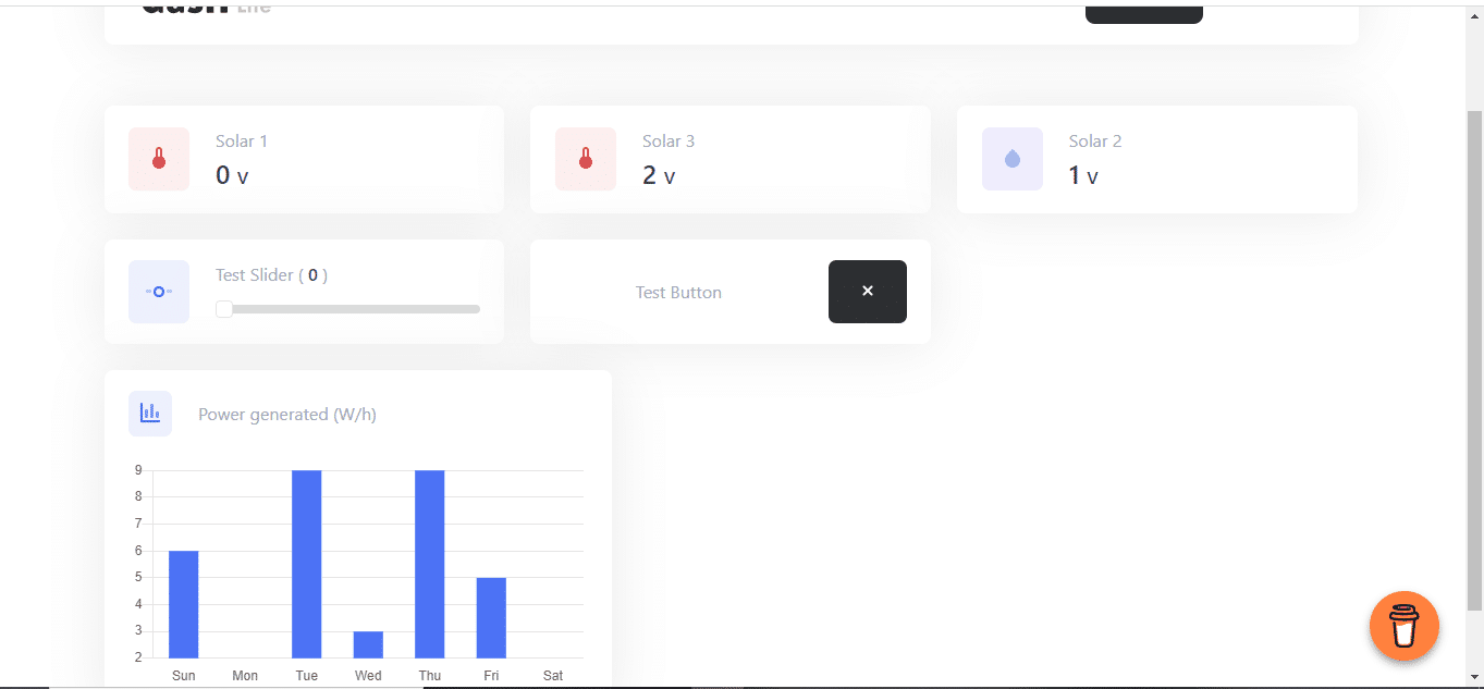
So in today’s project, you will learn to build an IoT solar monitoring system that maintains the overall solar-based electricity supply while consuming minimum power for its function. Based on the performance of each solar power unit, you will get a live graph and information on the amount of electricity required by clients. Using the dashboard, you can also monitor in real-time the power produced by each solar panel and track the efficiency of each solar panel.
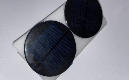
With that said, let’s start our project by collecting the following components.
Bill of Material

Programmer chips like FTDI, Arduino Uno etc, are optional.
Note: The above bill of materials is for one solar panel. For multiple ones, more is required. To monitor air quality, you can add an extra ADC input channel expansion chip such as ADS1115 16-bit ADC 4-channel I2C chip with the ESP. You will also need a voltage divider circuit for each solar panel.
Prerequisite
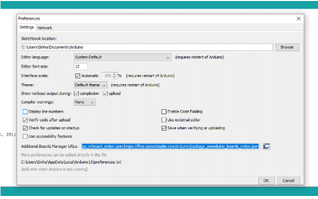
By default, the Arduino IDE doesn’t have an ESP board in its list of options. Therefore, to add an ESP board to the Arduino IDE, go to Preferences and then add this link.
Next, open Board Manager, search for ESP and install it in the Arduino IDE.
After installing the library in the code, install the dashboard library, and the OTA library along with other libraries required for the project using Library Manager.
Coding
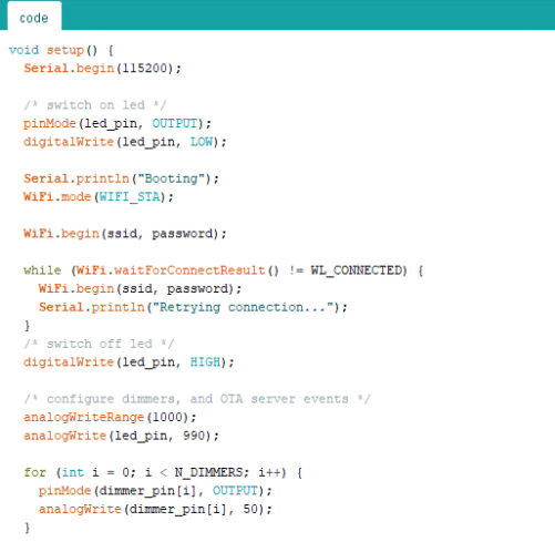
First, include the ArduinoOTA and the ESPDash libraries into the code.
Then define the pin numbers for sensing the power generated from the solar panel. Set the SSID (WiFi with which the system should connect) password and connect it to the network.

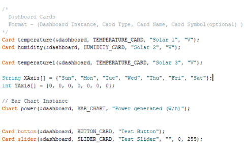
Now define the card (small dialog box) responsible for displaying the data related to the power generated by each solar panel. Here, the ESP dashboard gives you the option to add as many cards as you want.
For temperature and humidity cards, use the temperature and humidity generated by the atmosphere for displaying the power generated from the solar panel .
Now create a setup function for the basic checkup of the OTA firmware update. Check the graphs card and set the pin mode for ADC as INPUT.
Next, create a loop function to check the sensor pin. It will read the voltage produced by the solar panel and update it on the ESP dashboard.
Connection
For uploading the firmware to ESP, connect the FTDI as shown in the connection diagram. Press the button to select the correct part and board for uploading the code .
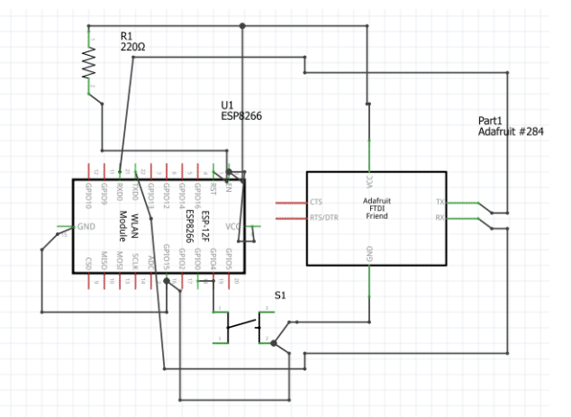
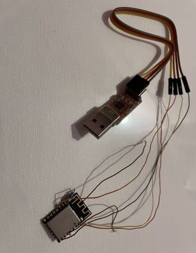
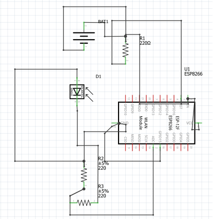
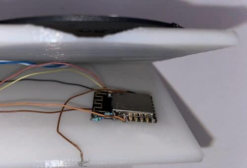
After uploading the code, power the ESP as shown in the connection diagram. Also connect the sensor pin of voltmeter to the ADC pin of ESP.
Testing

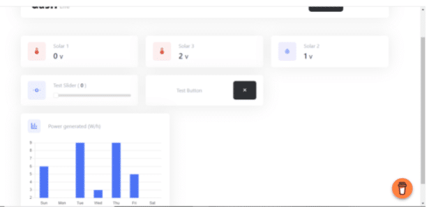
Open the IP address in a web browser to see the real-time solar panel performance graph. You can either add the ADC expansion chip and modify the code for collective monitoring of many solar panels or set up the ESP device (just like the previous method) for monitoring data of individual solar panels.


good but which IP address is used to calculate grah