 The influx of the Internet of things (IoT) devices has created a huge demand for connecting everything to everything. In the same race, this remote control for home appliances lets you connect your regular everyday appliances to be controlled by a remote. All you have to do is connect this circuit to any of your home appliances (lamp, fan, radio, etc) and you are good to go. The appliance can now be controlled by a remote control working at the designated frequency. The circuit can be activated from up to 10 metres.
Remote control for home appliances: Working Basics
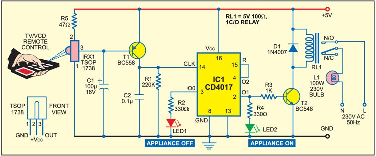
The 38kHz infrared (IR) rays generated by the remote control are received by IR receiver module TSOP1738 of the circuit. Pin 1 of TSOP1738 is connected to ground, pin 2 is connected to the power supply through resistor R5 and the output is taken from pin 3. The output signal is amplified by transistor T1 (BC558).
The amplified signal is fed to clock pin 14 of decade counter IC CD4017 (IC1). Pin 8 of IC1 is grounded, pin 16 is connected to Vcc and pin 3 is connected to LED1 (red), which glows to indicate that the appliance is ‘off.’
The output of IC1 is taken from its pin 2. LED2 (green) connected to pin 2 is used to indicate the ‘on’ state of the appliance. Transistor T2 (BC548) connected to pin 2 of IC1 drives relay RL1. Diode 1N4007 (D1) acts as a freewheeling diode. The appliance to be controlled is connected between the pole of the relay and neutral terminal of mains. It gets connected to live terminal of AC mains via normally opened (N/O) contact when the relay energises.
Circuit Diagram

Demo Video of Remote Control for Home Appliances (Credit: Sriram Karthik)
Hope this remote control for home appliances made your life a little easier. Another project titled make IR remote should also be helpful.
If you have any projects that you would like to share with the electronics engineering community please mention it in the comments below.


How to construct remote??
select remote
THIS PROJECT REMOTE CIRCUIT
You don’t need to construct remote control in this project. You can use any TV/VCR remote to operate the circuit. If you are really interested in making the remote control circuit, you can refer to “Design your own infra red remote” project published in EFY earlier.
the TSOP connections in this circuit is false.TSOP 2nd pin is always connected to ground. please check this circuit. thank you.
You are wrong. Pin2 of TSOP1738 used here should be connected to power supply Vs or Vcc. You can verify it by referring to its datasheet.
Our green LED doesn’t work it’s not glow even appliances is on !! What to do??
After constructing the circuit, While checking the operation with TV remote the LED1 and LED2 are getting turn On and OFF automatically without operating the Remote. I have verified circuit twice.
What could be the reason ?
I have same prblm
can u send me the remote codes
we want to make this project for controlling of 2-3 appliances
plz guide us and give ur valuable suggestion as soon as possible.
This circuit is designed for controlling only one appliance. For multiple appliance control, you may refer to “31 Channel RF remote control” project published in EFY March, 2013 issue.
Use microcontroller
may get PCB design for this project? if yes, please send link
We do not have PCB design for this circuit
do we need a transformer?
Kindly elaborate your query.
i have made this circuit as per circuit diagram but circuit is not working
kindli help please
tell all used component
hi, I buy a full kit and it’s working well but (sometimes not ever) it’s get inoperative (both led off) when I turn off the power, I have to used remote control to reinit (red led on).
I prepared a samsung power cell as 5v source.
Any suggestion ?
Thanks in advance.
can i use a zero watt bulb instead of led as a load ?
will it work when i use a 60 watt bulb as a load ?
It will work…60 watt bulb will take apporx 20 millamps
Hi,
After constructing the circuit, While checking the operation with TV remote the LED1 and LED2 are getting turn On and OFF automatically without operating the Remote. I have verified circuit multiple times.
Please help me.
Thank You.
can we control more than 1appliances with 1 circuit?
explain the working ? with simple words from starting
why ic cd4017 is used and what is its working, please also tell the role of bc558 and bc547,will it on and off with any button of remote or some specific button
please tell why we are using IC1 cd4017 what is its work and also tell why are using bc 548
it is very useful minor project for polytechnic students
Comment: I wish to get a remote sensor kit for normal water cooler to convert high tech as temperature control by frequent on off watering to save water and maintain temperature, remote oscilation speed and direction of air changer a perfume stick or gel for fragrence and sweet soothing sound for healthy sleep.
What is purpose of R1 220kohm resistor in this circuit??
It is used to prevent false triggering but can be omitted
can we use this circuit for more than1 lamp….and maximum how many lamps are controlled…??
can I get the code for this
can u pls send the link
sir, i use 4.5 v as a power supply. circuit is not working, what to do.
Where can I get explanation of whole circuit diagram in detail ??
please send me ful project of tv remot receiver and driving system for controlling home appliance?