 Normally exhaust fans installed in kitchens, including restaurant kitchens, keep running continuously—whether smoke is present or not. Here is how you can build a small electronic device that switches on the exhaust fan automatically only when there is smoke in the air. It switches the exhaust fan off when the smoke has been removed.
Circuit and working
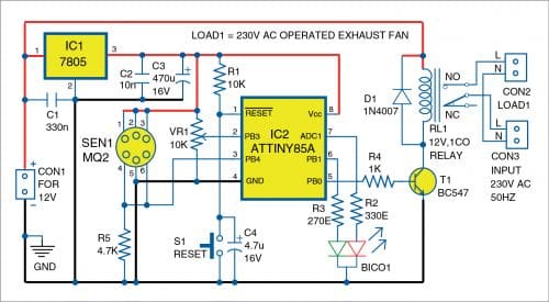
The circuit diagram of the auto exhaust fan switch is shown in Fig. 1. It has 5V voltage regulator 7805 (IC1), AVR microcontroller ATtiny85A (IC2), gas sensor MQ2 (SEN1), common-cathode bi-colour LED (BICO1), 5V single changeover relay (RL1), NPN transistor BC547 (T1), and a few other components.

The ATtiny85A turns the exhaust fan connected through the relay on or off based on extent of smoke in the air. The resistance offered by MQ2 sensor changes with smoke concentration near the sensor and thus changes voltage at analogue input pin 3 (PB4) of IC1. Potentiometer VR1 is used to adjust the sensitivity of the sensor during calibration.
When the circuit is powered on, bi-colour LED BICO1 blinks in red colour for 20 seconds, indicating that the circuit is in the necessary pre-heat stage (see Fig. 1). After that the microcontroller continuously checks whether voltage at analogue input (pin 3) is above the threshold value set using potentiometer VR1 during calibration. When the sensor detects sufficient smoke, its digital pin 5 (PB0) goes ‘high’ and energises the relay to turn on the exhaust fan connected at CON2. The bi-colour LED BICO1 glows continuously in red colour to indicate that smoke is present.
When the concentration of smoke near the sensor goes below the preset level, digital pin PB0 goes ‘low’ after one minute. The exhaust fan keeps running during this one minute to ensure smoke in the entire kitchen has been removed. During this one-minute period, BICO1 blinks in orange colour to indicate that the exhaust fan is now running to remove the smoke that may be present elsewhere in the kitchen. After this period, the digital pin goes low and de-energises the relay, which switches the exhaust fan off. Bi-colour LED BICO1 now emits green colour to indicate that no smoke is present in the air.
Pushbutton switch S1 can be used to reset the microcontroller. Capacitor C4 is used to debounce switch S1 and it helps in power-on resetting along with resistor R1.
Software
The source code ExhaustFanSwitch.ino is written in Arduino programming language using Arduino IDE. By default, Arduino IDE does not support ATtiny85, so ATtiny board needs to be added to Arduino IDE. To add ATtiny support to Arduino IDE, open FilePreferences and in the additional boards manager URLs, add the below URL.


couldn’t this project be done without any microcontroller? in my opinion, it looks like to prefer luxury a little bit, right? Because anymore its new habit (or fashion) to convert all analog circuits to programmed digital ones.
Engineering or designing is to do everything more basic, more cheap and more practical. what do you do such this?
The author Samiuddhin replies: Thank you for taking interest in my article. Yes, you can do this same function with digital IC’s but I designed with MCU based in my interest. The EFY magazine is read by all people from beginners to expert. The circuits published in the DIY section are focused for electronic enthusiast. That’s why this project is concept based and not based on cost effective, small size ..etc.,