

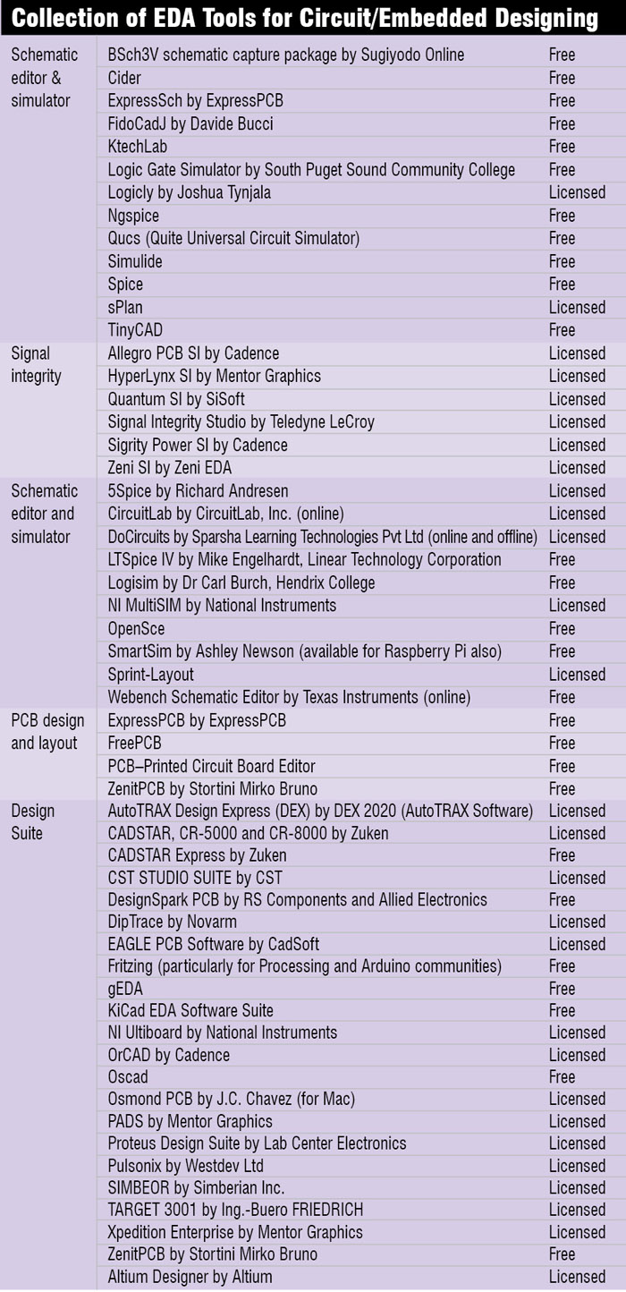
Creation of a device or instrument involves many stages, right from inception of the idea to getting the final product in hand. Many of these devices have been made simpler by using the free or licensed EDA tools available. Let us take a look at the different processes involved in an electronics design and the software used to automate these processes.
Normally, the steps that need to be taken for designing an electronic product are:
1. Capturing of product idea as schematic
2. Synchronising with printed circuit board (PCB) layout tool
3. Performing the layout (placement and routing)
4. Creating the manufacturing outputs
Circuit design and schematic entry
The process of designing standard circuit diagrams with related symbols and parameters is known as schematic capture or schematic entry. This is achieved with the help of an EDA software known as schematic editor. Present-day schematic editors also have some or all of the following features:
1. Extensive component libraries
2. Options to create and define your own components
3. Capabilities for hierarchical designing
4. Automatic detection of unfeasible connections and other errors
5. Documentation of circuit details and calculation of bill of materials
6. Creation of netlists and other commom formats for storing and transferring data related to the circuits

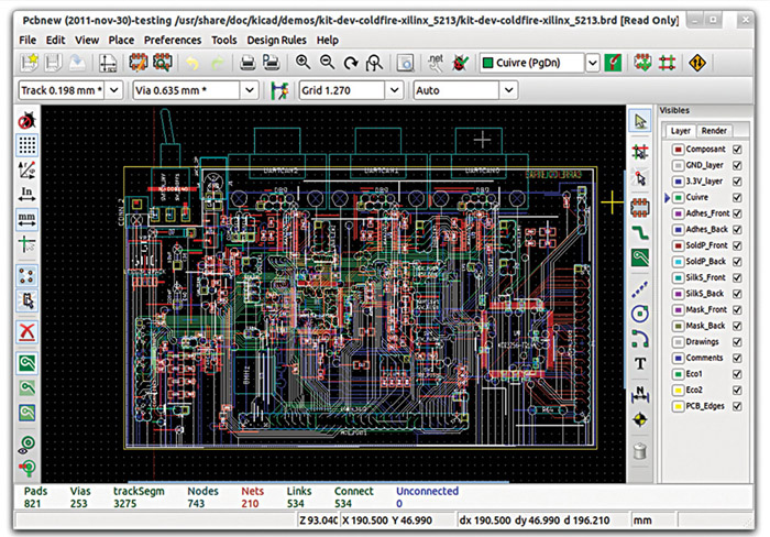
Creating a layout and printing it on board used to be a fully manual procedure but, thanks to the numerous PCB layout tools available these days, most of the steps in PCB layout creation and editing are automatic now.
For instance, the tools for signal integrity (SI) measure a set of parameters to check the quality of a PCB. Issues like transmission losses, cross-talk, impedance mismatch, thermal stress and strain etc are identified and steps taken to solve these before sending the product for manufacture. This reduces the failure rate of PCBs, thereby reducing time, effort, material and cost.
There are several design rules for minimum spacing between pads and traces, acute angle, minimum annular ring, drill-to-drill clearance etc, which determine whether a product can actually be manufactured properly. The computer-aided design (CAD) and computer-aided manufacturing (CAM) validation ensures that the design created is compatible with all these criteria and lets you create an optimised model. A netlist is generated from this software and sent to a manufacturer for PCB validation.
The right tool for you
So now you have an idea of the different steps of software-enabled circuit designing. The next question is how to select the right tool for your application? What all parameters are to be considered before going to the vendors?
Design complexity
The first and foremost parameter to consider is the kind of boards/products you want to design. If all the designs you expect to create are of less to medium complexity, you can go for relatively simpler, low-performance tools/suites like OrCAD, PADS or Proteus.
What your target customers use
It is necessary to understand the EDA products used by the service providers to whom you are delivering the design. If the customer uses one tool and you give them a design that cannot be compatible with that tool, you may lose the customer. Of course, there are other tools available online that can convert the output design file to a different format. But that requires more effort and time. So it is best to use the tools that are compatible with those used by your customers.
Product design
Some of the products put more emphasis on the electronics and electrical part; the physical form of the product is less important. Some other products have a prominent mechanical form and the electronics part is limited to a PCB and a couple of wires. Tools like Altium Designer and CR-8000 provide better integration or co-design of electronic CAD (ECAD) and mechanical CAD (MCAD) elements for designing the final product.
Cost
Price of the software tool(s) can be a constraint for start-ups, small and medium enterprises (SMEs) and academia. If the design complexity is less, one can always go for free and open source tools. Generally, paid-for tools offer more and better features besides the support required for complex designs. Tools like Allegro can be very expensive but price of CADSTAR is a bit on the lower side. The cost of Altium Designer is in between these two.


I need help because I am planning the take the course and studied get the certificate then I work to the company for internship. Because I am doing III year ece dept at kalasalingam University. the course is “OPEN SOURCE EDA TOOLS”. SO I need your help please contact the email and contact no:9789380839