


Voltage sources in a circuit may have fluctuations resulting in not providing fixed voltage outputs. A voltage regulator IC maintains the output voltage at a constant value. 7805 Voltage Regulator, a member of the 78xx series of fixed linear voltage regulators used to maintain such fluctuations, is a popular voltage regulator integrated circuit (IC).
The xx in 78xx indicates the output voltage it provides. 7805 IC provides +5 volts regulated power supply with provisions to add a heat sink.

7805 Voltage Regulator IC Specifications
- Minimum Input voltage is 7V
- Maximum Input Voltage is 35V
- Current rating Ic = 1A
- Maximum Output Voltage VMax=5.2V
- Minimum Output Voltage VMin=4.8V
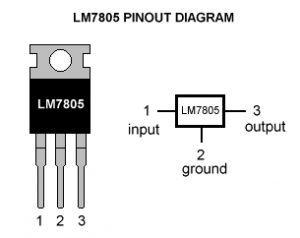
LM7805 Voltage Regulator Pinout
Below you can see the 7805 Voltage Regulator Pin Diagram.
| Pin No. | Pin | Function | Description |
| 1 | INPUT | Input voltage (7V-35V) | In this pin of the IC positive unregulated voltage is given in the regulation. |
| 2 | GROUND | Ground (0V) | In this pin where the ground is given. This pin is neutral for equally the input and output. |
| 3 | OUTPUT | Regulated output; 5V (4.8V-5.2V) | The output of the regulated 5V is taken out at this pin of the IC regulator. |
As you may have noticed, there is a significant difference between the input voltage & the output voltage of the voltage regulator. This difference between the input and output voltage is released as heat. The greater the difference between the input and output voltage, more the heat is generated.
If the regulator does not have a heat sink to dissipate this heat, it can get destroyed and malfunction. Hence, it is advisable to limit the voltage to a maximum of 2-3 volts above the output voltage.
So, we now have 2 options. Either design your circuit so that the input voltage going into the regulator is limited to 2-3 volts above the output regulated voltage or place an appropriate heatsink, that can efficiently dissipate heat.
7805 IC Heating Problem
7805 voltage regulator is not very efficient and has drop-out voltage problems. A lot of energy is wasted in the form of heat. If you are going to be using a heatsink, better calculate the heatsink size properly. The below formula should help in determining the appropriate heatsink size for such applications.
Heat generated = (input voltage – 5) x output current
If we have a system with an input of 15 volts and the output current required is .5 amperes,
Then we have: (15 – 5) x 0.5 = 10×0.5 = 5W;
5W energy is being wasted as heat, hence an appropriate heatsink is required to disperse this heat. On the other hand, the energy actually being used is: (5 x 0.5Amp) = 2.5W.
So twice the energy, that is actually utilized is wasted. On the other hand, if 9V is given as input at the same amount of load: (9-5) x 0.5 = 2W
2W energy will be wasted as heat.
What should we do then?
Remember… higher the input voltage, the less efficient your IC7805 will be.
An estimated efficient input voltage would be about 7.5V.
Why do we use Capacitors with 7805?
If your voltage regulator is situated more than 25cm (10 inches) from the power supply, capacitors are needed to filter residual AC noise. Voltage regulators work efficiently on a clean DC signal being fed. The bypass capacitors help reduce AC ripple.
Essentially, they short AC noise from the voltage signal and allow only DC voltage into the regulator. The two capacitors are not necessarily required and can be omitted if you are not concerned about line noise.
However, for a mobile phone charger or logic assessment, you require a nice clean DC line. Capacitors will be beneficial in this case as they are good at maximizing voltage regulation. The values of capacitors can also be changed slightly.
You can check Why Are Filter Capacitors Used in Some Battery Charger Circuits?
Let’s take a look at what makes the IC tick.
Voltage Regulator 7805 IC Circuit
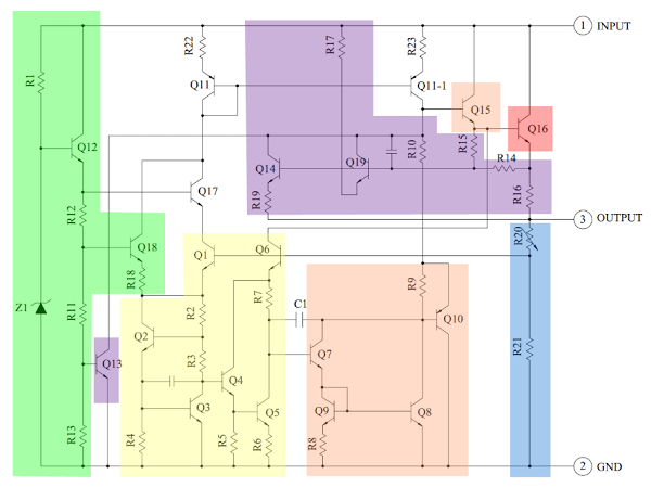
The heart of the 7805 IC is a transistor (Q16) that controls the current between the input and output and thus controls the output voltage. The bandgap reference (yellow) keeps the voltage stable.
It takes the scaled output voltage as input (Q1 and Q6) and provides an error signal (to Q7) for indication if the voltage is too high or low.
The key task of the bandgap is to provide a stable and accurate reference, even as the chip’s temperature changes.
The error signal from the bandgap reference is amplified by the error amplifier (orange). This amplified signal controls the output transistor through Q15. This closes the negative feedback loop controlling the output voltage.
The startup circuit (green) provides initial current to the bandgap circuit, so it doesn’t get stuck in an “off” state. The circuit in purple provides protection against overheating (Q13), excessive input voltage (Q19), and excessive output current (Q14).
These circuits reduce the output current or shut down the regulator, protecting it from damage in case of a fault. The voltage divider (blue) scales down the voltage on the output pin for use by the bandgap reference.
Scaling the Output
The 7805’s scaled output provides the input voltage (Vin) to the bandgap reference and the bandgap provides an error signal as the output. The 7805’s bandgap circuit removes the feedback loop that exists inside a traditional bandgap reference. Instead, the entire chip becomes the feedback loop.
If the output voltage is correct (5V), then the voltage divider provides 3.75V at Vin. Any change in output voltage propagates through Q6 and R7, causing the voltage at the base of Q7 to rise or fall accordingly.
This change is amplified by Q7 and Q8, generating the error output. The error output, in turn, decreases or increases the current through the output transistor. The negative feedback loop adjusts the output voltage until it is correct.
IC 7805 Voltage Regulator Applications
7805 IC is used in a wide range of circuits. The major ones are:
- Fixed-Output Regulator
- Positive voltage Regulator in Negative voltage Configuration
- Adjustable Output Regulator
- Current Regulator
- Adjustable DC Voltage Regulator
- Regulated Dual-Supply
- Output Polarity-Reversal-Protection Circuit
- Reverse bias projection Circuit
7805 Voltage regulator also finds usage in building circuits for inductance meters, phone chargers, portable CD player, infrared remote-control extension, and UPS power supply circuits. Also, we designed a Stopwatch Circuit using IC7805.
The slideshow below also highlights some points with voltage regulators.
Complete technical detailed information about the 7805-voltage regulator IC can be found in the 7805 IC datasheet.
What does a 7805 voltage regulator do?
A 7805 voltage regulator is an integrated circuit designed to maintain a constant output voltage despite changes in input voltage and load. Specifically, the 7805 is a positive voltage regulator that ensures a stable +5V output, making it a popular choice for powering various electronic components and circuits.
How much voltage can 7805 handle?
The 7805 voltage regulator is typically used to provide a fixed +5V output. To ensure proper operation, the input voltage should be higher than the desired output voltage plus a small overhead voltage for the regulator to function correctly. Generally, the input voltage can range from around 7V to 35V, allowing the 7805 to handle a wide range of input voltages while maintaining a steady +5V output.
What temperature should a 7805 voltage regulator be?
The operating temperature of a 7805 voltage regulator is typically specified by its manufacturer. Standard operating temperature ranges are often from 0°C to 125°C. However, variations exist, and some models might have extended temperature ranges to accommodate specific applications.
What is the difference between LM7805 and 7805?
The terms “LM7805” and “7805” both refer to the same type of voltage regulator. The LM prefix indicates that the component is manufactured by National Semiconductor (now a part of Texas Instruments), and it’s often included for clarity. So, the LM7805 and 7805 both represent the same voltage regulator with a fixed +5V output.

I think your articles have been written by someone who is not a native English-speaker.
Perhaps an editor would clear this up.
Thank you!
Steve Satak
Thank you for pointing it out Steve. We are all non native english speaking people here.
However, we have updated the article. Hope it suits your requirements.
very good as however for a amateur a pinout diagram is missing to know witch is pin1 ,2or 3
What is impact due to current in these cases
1. Output of 5v from ac to dc wall mobile charger something says 5v 500mA output
2. 7805 voltage regulator ic says 5v up to 1A and
3. 5v from arduino which says 5v max 40ma … ?
To which say pir is attached which works at 5 to 12 v is different current will burn my pir sensor or it will just work fine and use it’s required current ?
Sir i made a voltage regulator using 7805 ic for powering my microcontroller but my chip isnt working
Plz tell me where i m wrong
Add a capacitor to input and output with values 0.33 uf and 0.1 if respectively if your power source is at a distance.
I have used a full bridge rectifier along wd a 909 transformer i tried to connect .01 uf @ ouput nd inputs of d 7805 then i disconnected d caps nd connected .46 uf nd .1 uf d ouput terminals i also changed d value to 470 uf but still d microcontroller isnt working i checked d voltage which was 5.21 v at 200vac plz tell me what should i do..
Thanks
good one
Comment:thank you
7805 regulator shows less than 5 V in the circuit (2.7 V), but if you remove the solder and put it in a bread board it shows 5 V, there is no bad connection in the circuit and all solders are good, but the problem persists, could you tell me why?
I have 78M05 IC in D pak package.some times it didn’t shows input and o/p voltage and because of this pcb off.our pcb is working on 17v input at 7805 IC and output is 5V.we are using capacitor 220uf and 100uf near input and o/p.
please suggest where is exact problem?
What BJT’s where used to internally construct the LM7805 and what zener diodes?
Very helpful material
Thank you for your feedback.
Thanks for the details. The voltage regulator produces constant output voltage of 5v with operating range input of 7-40v. Does this IC boost voltage input is voltage is less than 5 ?
If not, I am looking for an IC which has Operating range from 3-30v and constant 5v output.
Any body can tell me why my 7805 ic gives only 300ma . I connect two ic but it gives 300ma???
Is there any simple regulator like 78xx but which does not waste such a large amount of power into undesirable heat?
Please comment on which pin # the TAB is electrically tied to. In fixed voltage regulators it is usually Gnd (pin2), but don’t assume. The heat sink you attach it to is often at GND. But don’t assume. 🙂
A helpful and interesting article. Thank you
You are most welcome.
Thanks so much for details GOD Bless you. I wish to ask if the regulator can regulate 4v to constant 5v and how are the filter capacitors conected and which value is good for the circute
good article, thanks for all your efforts.
Thank-you
You are welcome.
Hi!
GROUND: “This pin is neutral for equally the input and output.”
I’m just found a video, where a guy added two diode to the ground, which solution is increase the voltage level to 6v.
Here’s a link about this:
https://www.youtube.com/watch?v=YxeJaUNWdA4
Actually I don’t understand what’s happens, but works. My question is:
How is it possible? Other question is: This is a good solution, or not?
Cheers:
Adam
I made a voltage regulator with the LM7805 and the voltage and the current ware not stable on load, dough my input current voltage too is not stable, so how do I stabilize the output with the unstable input