


 Arduino is very helpful for people who have little knowledge of programming or electronics. The user does not need to understand the hardware or the low level coding of the AVR controller.
Arduino is easy to use and can be learned with very little effort. Hence, the development/prototyping time using Arduino is considerably less. Arduino is based on WinAVR, a gcc compiler for AVR. You can create an Arduino project in Atmel Studio and even simulate it.
At present Arduino uses ATmega328, ATmega168, ATmega1280, ATmega2560 and ATmega8 boards/controllers. However, many users/developers are using ATmega32 controller in their projects now and are more familiar with this controller. But it is not seen in the list of Arduino boards in Arduino IDE.

ATmega32 has 32 general-purpose input/output (GPIO) pins, which is more than 20 used in ATmega328. It is disappointing that some boards have more I/O pins, like ATmega1280 and ATmega 2560, but are expensive.
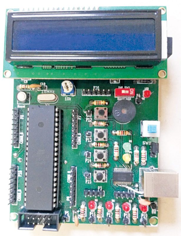
In this project, we use ATmega32 as a microcontroller (MCU) in Arduino board and utilise almost all the 32 GPIO pins available as shown in Fig.1. Author’s prototype is shown in Fig. 2.

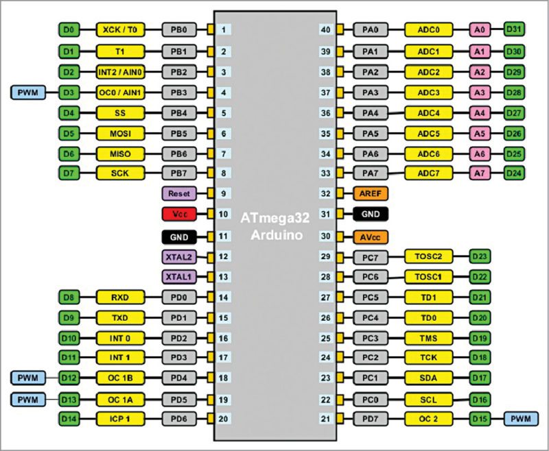
Pinout of ATmega32 as used in Arduino board
- Thirty two digital pins (D0 to D31)
- Eight analogue-to-digital pins (A0 to A7); these can be used as digital pins also
- Four PWM pins
- Other pin details in Fig. 1
Circuit and working
LCD interface: Normally, Arduino boards do not have an LCD on board. However, for development work it is very essential. Provision of an onboard LCD is very easy because no extra wiring or component is required; only data pins are to be connected.
Push-to-on switches: Four push-to-on switches are provided onboard for testing purpose; no extra wiring is required, hence testing is fast and easy.
LEDs: Four LEDs are provided onboard for easy and fast testing.
Buzzer: This is provided to test sketches using tones in Arduino.
Power supply: Vcc and ground pin headers (four pins each) are provided for extending the supply voltage and ground pins while testing.
Other provisions: All other provisions like digital pins and analogue pins are available as on any other Arduino board.
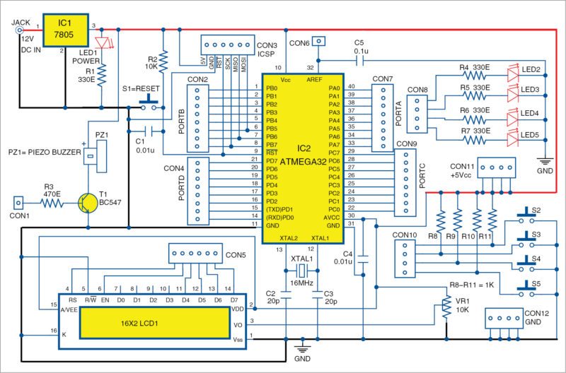
The detailed circuit diagram of Arduino for ATmega32 is shown in Fig. 3.
Software
Arduino software version 1.0.5 has some directories. For making it suitable for ATmega32 we have to modify/add some directories/files to it. The directory structure is given in Fig. 4.
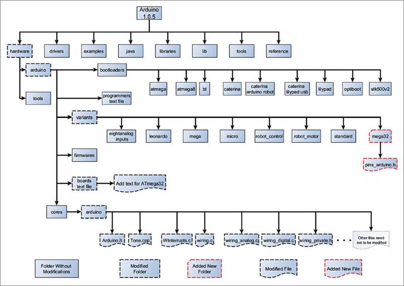
Check which directory/file needs to be modified/added. Details of modifications, that is, where/which lines are to be changed/added are given here for reference.
But first make a copy of Arduino version 1.0.5 software and make required changes in it. If you do not have 1.0.5 version, go to www.arduino.cc and click Download Link. From Previous Release box click Arduino 1.0.x and then click Windows option for version 1.0.5. Save this file and expand it.
Follow the instructions given below for making modifications
Directory structure of Arduino: Go through it and verify it with Arduino version 1.0.5 so that you get overall idea of the changes required in the files and folders of Arduino. For editing relevant files (like boards.txt, pins_arduino.h and so on), use Programmer’s Notepad and use/toggle line number display so that you can view line numbers in the opened file.
Modify the files in this directory structure as per the steps below.
Go to Hardware\Arduino directory: Open the text file named boards.txt and add the following lines at the end of this file:
atmega32.name=Arduino ATmega32
atmega32.upload.protocol=arduino
atmega32.upload.maximum_size=30720
atmega32.upload.speed=19200
atmega32.bootloader.low_fuses=0xFF
atmega32.bootloader.high_fuses=0xCA
atmega32.bootloader.path=atmega32
atmega32.bootloader.file=ATmega32BOOT.hex
atmega32.bootloader.unlock_bits=0x3F
atmega32.bootloader.lock_bits=0xCF
atmega32.build.mcu=atmega32
atmega32.build.f_cpu=16000000L
atmega32.build.core=arduino
atmega32.build.variant=mega32
Define the hardware of ATmega32: For this, search for directory location hardware\arduino\varients and create a new directory named mega32. Inside this new directory, add a new file named pins_arduino.h by copying it from Standard Directory.
This file includes digital pins, analogue pins, timer pins, pwm pins, ports and port bits. The numbers of digital pins, analogue pins and pwm pins are changed as below:
#define NUM_DIGITAL_PINS 32
#define NUM_ANALOG_INPUTS 8
#define analogInputToDigitalPin(p) ((p
< 8) ? (p) + 24 : -1)
#define digitalPinHasPWM(p) ((p) == 3 ||
(p) == 12 || (p) == 13 || (p) == 15)
Pin change interrupt (PCINT) is removed as it is not applicable for ATmega32. Constants are changed, that is, change for SS, MOSI, MISO, SCK, SDA and SCL as per ATmega32 hardware pin out.
static const uint8_t SS = 4;
static const uint8_t MOSI = 5;
static const uint8_t MISO = 6;
static const uint8_t SCK = 7;
static const uint8_t SDA = 17;
static const uint8_t SCL = 16;
Constants for analogue pins are defined as follows:
static const uint8_t A0 = 31;
static const uint8_t A1 = 30;
static const uint8_t A2 = 29;
static const uint8_t A3 = 28;
static const uint8_t A4 = 27;
static const uint8_t A5 = 26;
static const uint8_t A6 = 25;
static const uint8_t A7 = 24;
Remaining modifications can be made as given below:
const uint16_t PROGMEM port_to_mode
_PGM[] = {
NOT_A_PORT,
(uint16_t) &DDRA,
(uint16_t) &DDRB,
(uint16_t) &DDRC,
(uint16_t) &DDRD,
};
const uint16_t PROGMEM port_to_
output_PGM[] = {
NOT_A_PORT,
(uint16_t) &PORTA,
(uint16_t) &PORTB,
(uint16_t) &PORTC,
(uint16_t) &PORTD,
};
const uint16_t PROGMEM port_to_input
_PGM[] = {
NOT_A_PORT,
(uint16_t) &PINA,
(uint16_t) &PINB,
(uint16_t) &PINC,
(uint16_t) &PIND,
};
const uint8_t PROGMEM digital_pin_to_
port_PGM[] = {
PB, /* B *0* */
PB,
PB,
PB,
PB,
PB,
PB,
PB,
PD, /* D *8* */
PD,
PD,
PD,
PD,
PD,
PD,
PD,
PC, /* C *16* */
PC,
PC,
PC,
PC,
PC,
PC,
PC,
PA, /* A *24* */
PA,
PA,
PA,
PA,
PA,
PA,
PA,
};
const uint8_t PROGMEM digital_pin_to_
bit_mask_PGM[] = {
_BV(0), /* digital pin 0, port
B */
_BV(1), //digital pin 1
_BV(2), //digital pin 2
_BV(3), //digital pin 3
_BV(4), //digital pin 4
_BV(5), //digital pin 5
_BV(6), //digital pin 6
_BV(7), //digital pin 7
_BV(0), /* digital pin 8, port
D */
_BV(1), //digital pin 9
_BV(2), //digital pin 10
_BV(3), //digital pin 11
_BV(4), //digital pin 12
_BV(5), //digital pin 13
_BV(6), //digital pin 14
_BV(7), //digital pin 15
_BV(0), /*digital pin 16, port
C */
_BV(1), //digital pin 17
_BV(2), //digital pin 18
_BV(3), //digital pin 19
_BV(4), //digital pin 20
_BV(5), //digital pin 21
_BV(6), //digital pin 22
_BV(7), //digital pin 23
_BV(7), /* digital pin 24,
port A, note descending order */
_BV(6), //digital pin 25
_BV(5), //digital pin 26
_BV(4), //digital pin 27
_BV(3), //digital pin 28
_BV(2), //digital pin 29
_BV(1), //digital pin 30
_BV(0), //digital pin 31
};
const uint8_t PROGMEM digital_pin_to_
timer_PGM[] = {
NOT_ON_TIMER, /* 0 – port B */
NOT_ON_TIMER, /*1*/
NOT_ON_TIMER, /*2*/
TIMER0 , /*3 8 bit*/
NOT_ON_TIMER, /*4*/
NOT_ON_TIMER, /*5*/
NOT_ON_TIMER, /*6*/
NOT_ON_TIMER, /*7*/
NOT_ON_TIMER, /* 8 – port D */
NOT_ON_TIMER, /*9*/
NOT_ON_TIMER, /*10*/
NOT_ON_TIMER, /*11*/
TIMER1B, /*12*/
TIMER1A, /*13*/
NOT_ON_TIMER, /*14*/
TIMER2, /*15* 8 bit/
NOT_ON_TIMER, /* 16 – port C */
NOT_ON_TIMER, /*17*/
NOT_ON_TIMER, /*18*/
NOT_ON_TIMER, /*19*/
NOT_ON_TIMER, /*20*/
NOT_ON_TIMER, /*21*/
NOT_ON_TIMER, /*22*/
NOT_ON_TIMER, /*23*/
NOT_ON_TIMER, /* 24 – port A */
NOT_ON_TIMER, /*25*/
NOT_ON_TIMER, /*26*/
NOT_ON_TIMER, /*27*/
NOT_ON_TIMER, /*28*/
NOT_ON_TIMER, /*29*/
NOT_ON_TIMER, /*30*/
NOT_ON_TIMER, /*31*/
};
Search for hardware\arduino\cores\arduino directory. Open Arduino.h file and add the following line after the last timer-defined line, that is, after #define TIMER5C 17, which comes after line number 184.
#define TIMER0 18
Open Tone.cpp file in the cores directory and add/modify the following to suit Timer2 of ATmega32.
After line number 39, add defined(__AVR_ATmega32__) as shown below:
#if defined(__AVR_ATmega8__) || defined(__
AVR_ATmega128__) ||defined(__AVR_
ATmega32__)
After line number 56, add !defined(__AVR_ATmega32__) as shown below:
#if !defined(__AVR_ATmega8__) ||
!defined(__AVR_ATmega32__)
After line number 96, add defined(__AVR_ATmega32__) as shown below:
#elif defined(__AVR_ATmega8__) ||
defined(__AVR_ATmega32__)
Open WInterrupts.c in the same cores directory and add following for ATmega32 int2 after line number 147:
#elif defined(MCUCSR) && defined(ISC2)
MCUCSR = (MCUCSR & ~(1
<< ISC2)) | ((mode & 1) << ISC2);
GICR |= (1 << INT2);
After line number 324 add:
if defined(ISC2)
ISR(INT2_vect){
if(intFunc[EXTERNAL_INT_2])
intFunc[EXTERNAL_INT_2]();
}
#endif
Open wiring.c in the same directory cores and add following after line number 201:
#if defined(TCCR0) && defined(WGM00) &&
defined(WGM01)
sbi(TCCR0,WGM00);
sbi(TCCR0,WGM01);
#endif
In the same directory open Wiring_analog.c and add following after line number 129:
#if defined(__AVR_ATmega32__)
case TIMER0:
sbi(TCCR0, COM01);
OCR0 = val; // set pwm duty
break;
#endif
In the same directory open Wiring_digital.c and add following after line number 98:
#if defined(TCCR0) && (COM01)
case TIMER0:
cbi(TCCR0, COM01);
break;
#endif
In the same directory open wiring_private.h and add following after line number 56:
#elif defined(__AVR_ATmega1284__) || defined(__
AVR_ATmega1284P__) || defined(__
AVR_ATmega644__) || defined(__
AVR_ ATmega644A__) || defined(__
AVR_ ATmega644P__) || defined(__
AVR_ ATmega644PA__) || defined(__
AVR_ ATmega32__)
These modifications are sufficient. You can now select Arduino ATmega32 under Tools>Board on Arduino IDE 1.0.5 as shown in Fig. 5. You may perform all the steps for ATmega32 on this IDE like any other Arduino board. But with this you cannot load the sketches without an external programmer because we have not loaded bootloader on ATmega32 yet.
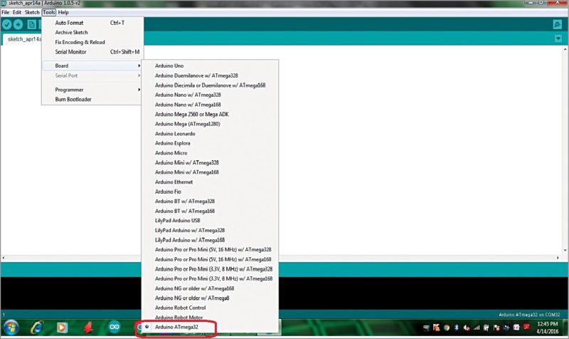
However, without the bootloader, it is also advantageous as full memory space is available for sketches\application programs on ATmega32. If we use bootloader, it will consume 2k memory of ATmega32.
With this project, you can use Arduino IDE for various designing purposes using ATmega32 MCUs.
Construction and testing
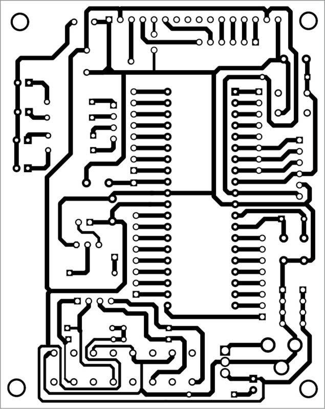
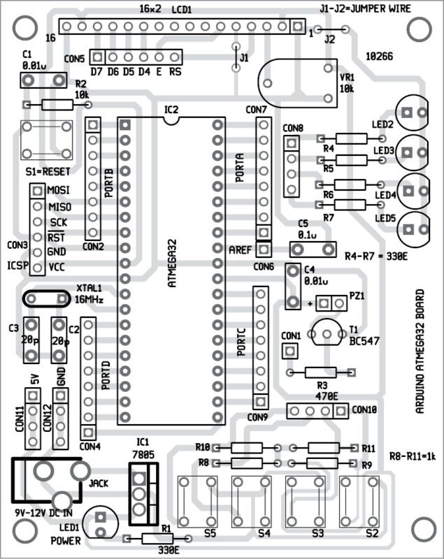
A single side PCB pattern of Arduino on ATmega32 circuit is shown in Fig. 7 and its component layout in Fig. 8. Assemble the circuit on the PCB as it minimises time and assembly errors. Carefully assemble the components and double-check for any error(s). Use proper IC base for the MCU. Test different programs like digital read, analogue read, LCD display, serial display, tone, etc using ATmega32 for Arduino with all 32 GPIO pins.
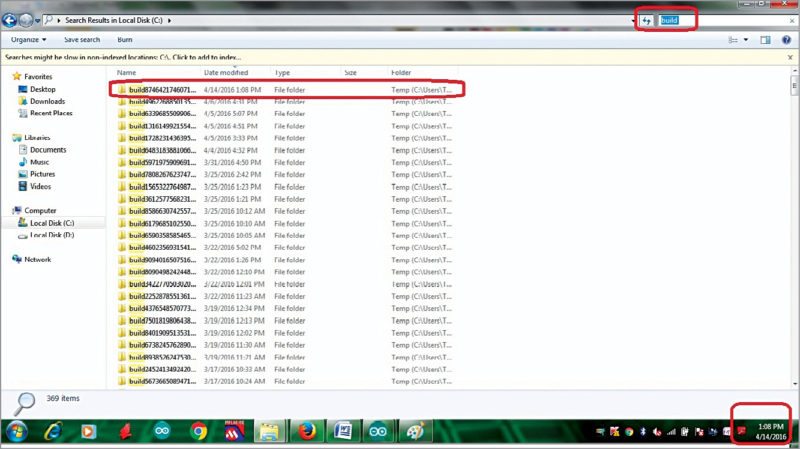
The hex file generated (after compiling the sketch for Arduino board using ATmega32) on Arduino 1.0.5 IDE can be obtained by searching the build folder in C:// as shown in Fig. 6.
You may connect an external programmer to CON3 in Arduino ATmega32 board to burn the hex file into ATmega32.
You can also change any future version of Arduino for ATmega32 once you understand how to change the corresponding files in that version.
Download PCB and component layout PDFs: click here
Download source code: Click here
Note: Your code may not match the line numbers mentioned in this article.
Check out more such Arduino projects.


Why can’t we use latest Arduino IDE?
The author was suppose to add the design with FT232 USB to ttl converter.
as the prototype image is with the FT232.
Dear sir ,
Can u suggest me Embedded C language books for the Arduino compatibility. for practices based purpose or student level.
Sorry, we cannot help you personally but we’d recommend you to join our forum (https://www.electronicsforu.com/forums) and post your question there. Our community members could help you out.
Sir the article is excellent, however just like the prototype board we would like to use an FTDI chip to program it directly using a USB, please contact.
good article
Can I use atmega16 also
Yes, you can use ATmega16 also