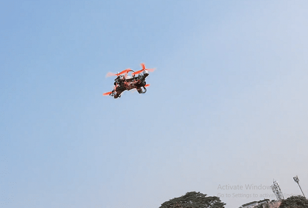
 Due to very high speed in small packages, the racing drones are very expensive starting from 25k to 70K and it becomes the question of affordability for those who are new to drone because during flight or racing if the drone gets crashed it becomes hard to replace the expensive parts.
Along with this we also do not have the flexibility to design as per our choice add the extra functionality as per our choice. So today we will make a racing drone in just around 15K with some lowest cost parts and upgrade it whenever we want with high-performance parts as per choice.
Here We are going to use the low-cost 2200kv 6T motor and CC3D Open pilot flight controller with Qav250 frame and 6045 ie 6-inch propeller for the drone and this combination makes it a perfect low-cost racing drone.
If you need to know how to select the motor and propeller battery ESC for Drone you can check the previous built F450 Drone.
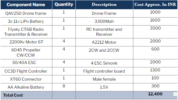
Bill of Materials
Let’s start the project by shopping for the following components:
Assembling The Drone
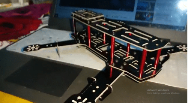
First of all we need to assemble the frame of Drone. The Qav250 drone frame consists of 2 base plates and 4 arms for the motor and 1 top plate and 4 landing gears, So first we place all the four arms for the motor in between the sandwich of two base plates and then we screw them.
Next, we will add the landing gears in the arm and then we will fix the top plate on the base plate and now our Frame is ready to equipped with the components. As you can see in the pic below the assembled frame.
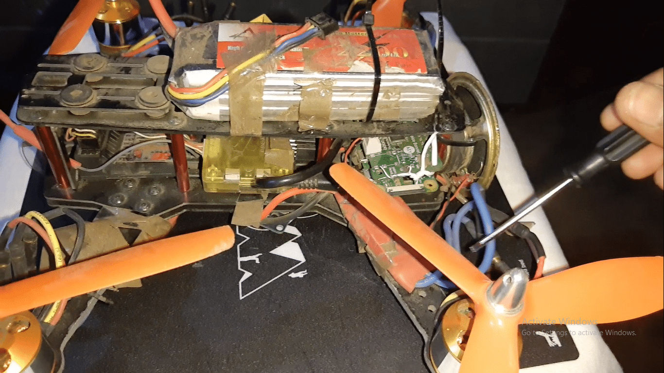
Next we connect the ESC wires to the Power distribution board along with the XT60 Plug according to the pic below. After that, We place the Power distribution board in the middle of the Qav450 Frame and then fix them. Next, we will fix the ESC on each arm of the Quad 250 frame as in the pic below. After that, we screw all 2200kv A2212 motors on the drone frame.
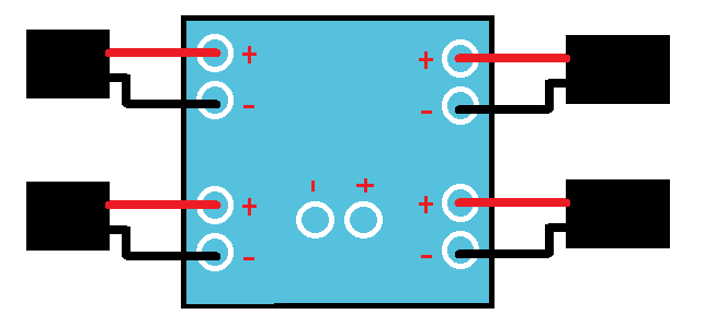
Connection
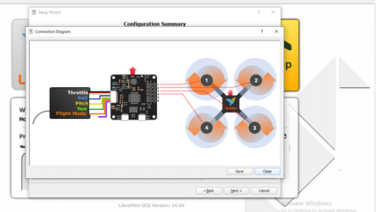
Now connect the ESC(side having 3) wire to Motor to motors 3 wires respectively with all the 4 motors and 4 ESC. Next, connect the ESC 3 wire Servo type pin to CC3D flight controller pins matching the + and -V notation on the CC3D pin side. GND connect black + connect to positive red of ESC and yellow to PWM signal. The Flight controller pins have signs of pins noted on the board. Next, connect the radio receiver to the CC3d Flight controller as in the pin diagram given below.
Preparing The CC3D Flight Controller
The CC3D Flight Controller can be programmed and prepared using the OpenPilot Ground Control Station or LibrePilot GCS. You can download any one of them.
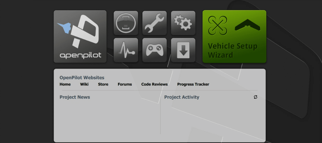
Here I have chosen to install the OpenPilot GCS. Now open the app and connect the CC3D Flight controller to a PC via a USB. Next, open the LibrePilot software and go to Vehicle Setup Wizard.
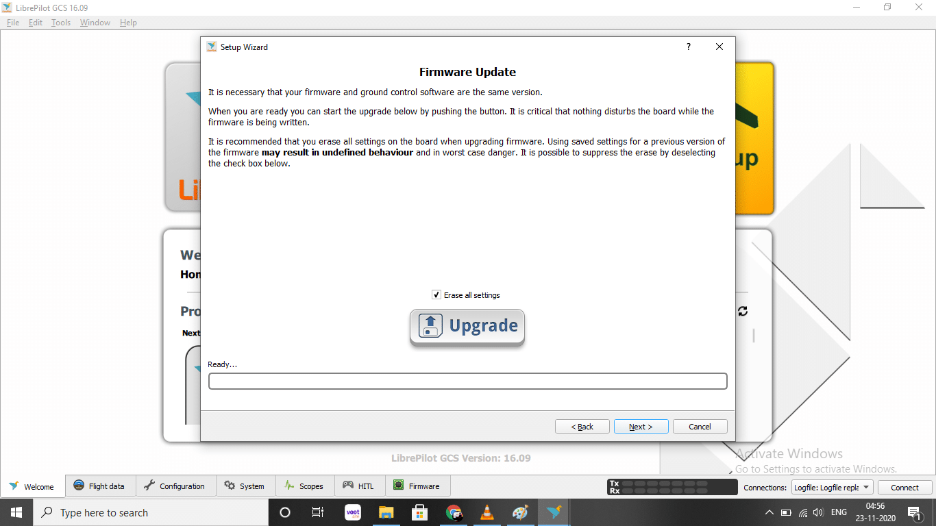
From the range of options, choose to update the firmware by clicking on Upgrade and then wait for the firmware to upload on the flight controller
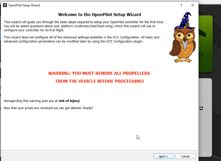
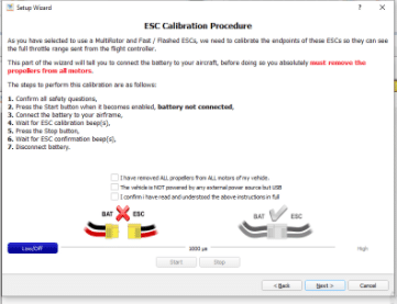
You will now get a window where you can enter in ACC calibration. Put the flight controller on a flat surface and make sure it is facing towards the front motor. Calibrate the accelerometer and the motor ESC as per the given instruction. Disconnect the battery from the power distribution board.
Now click on start and wait for a beep sound from the motor. Repeat the procedure once again. The ESC is now calibrated.
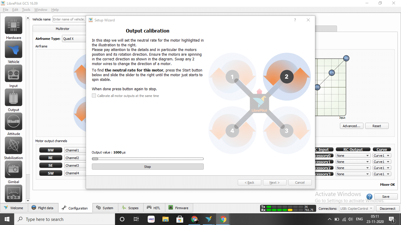
You are then taken to another window for output calibration. Here the rotational direction of a motor is shown. Click on start and then move the sliders until a motor starts moving smoothly. Then click stop. Ensure that the rotational direction of a motor matches with that shown in the image. If not, then swipe any two wirings of the motor to ESC to change the rotational direction.
Repeat the procedure for all motors and save the settings.
Next it will take you to the transmitter receiver setup wizard. Make sure that the transmitter remote is on, the receiver is connected and the LiPo battery is connected to the power distribution board. Follow the instructions given by the software.
Move the remote sticks as shown in the GUI and then put all the sticks at the centre. Next, move all the sticks to the max positions in both directions and save the settings.
After that, define the process for arming the flight controller. To do so, go to the arming settings and select the options for arming.
The Tricky Part of Arming on CC3D
It was noticed that the CC3D will not arm when the yaw stick is moved to the right. Even after trying different stick settings like pitch right and yaw left, nothing armed the flight controller.
Note: In fact, a quick search on the internet showed that many people are facing the same problem. I tried to figure out a solution to this problem and made many changes related to arming like changing the receiver values and trimming the radio remote. However, this part still remains to be quite challenging. But this can be done easily by using extra channels on remote like i have used the 6th channel for arming
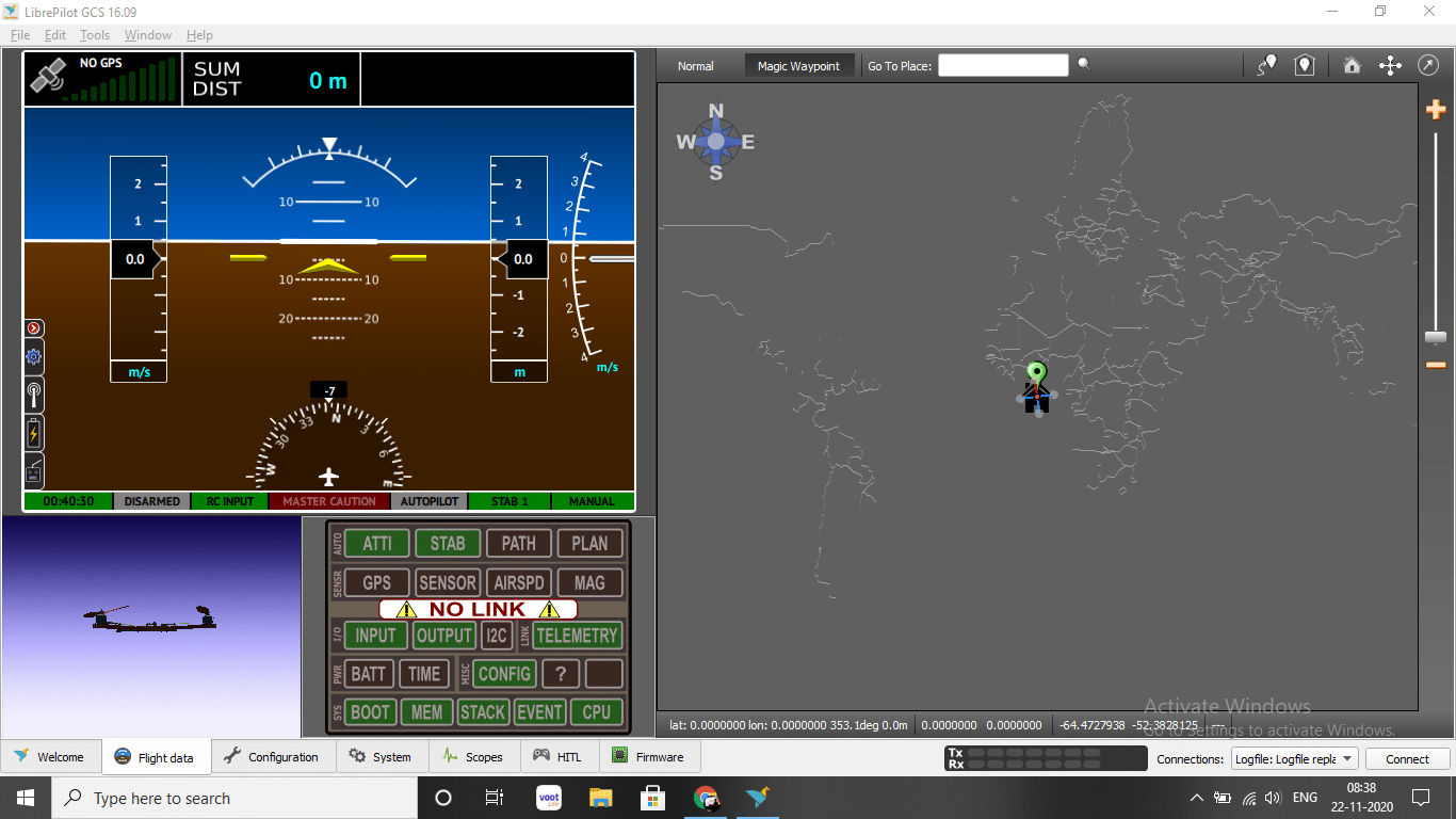
Adding The Camera
Next We can add the FPV camera to drone The FPV camera Have 3 wires yellow , Red , Black
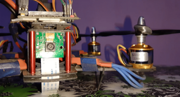
Connect the Red and Black wire with power supply according to the requirement of your . camera.Here I am using the The Raspberry Pi as webcam to save some extra cost as I all ready have the raspberry pi cam.I can get its video using VNC server connected to WiFi
Testing
Congrats!! Your drone is ready to fly .Now power board using the lipo battery attached using the XT60 connector and the arm of the drone as per your arm setting and now you are ready to fly the racing . You can connect the raspberry pi to pc see the video of the camera on drone .
