


Since there is no unique solution for a particular RF applications, some guidelines are needed. This article looks at some such guidelines.
An antenna transmits and receives electromagnetic (EM) radiation in free space. The wireless range of an antenna depends greatly on its design, enclosure and a good PCB layout. This article covers some of the best practices for antenna design for radio frequency (RF) applications, to get the widest range possible with a given amount of power.
Other general design considerations include antenna length and feed, shape and size of ground plane, and return path. Selection of an antenna depends on application, available board size, RF range, directivity and cost. For example, a Bluetooth mouse works in 30cm range and requires a data rate of only a few kbps, while a voice-controlled device requires 60cm range and a data rate of 64kbps.

Chip antennae are a good solution for applications where PCB size is extremely small. However, these increase the bill of material (BOM) and assembly expenses. These are sensitive to RF ground size, and require an additional matching network for antenna tuning, as the same cannot be achieved by changing antenna length. This further increases BOM cost.
Effects of enclosure and ground plane
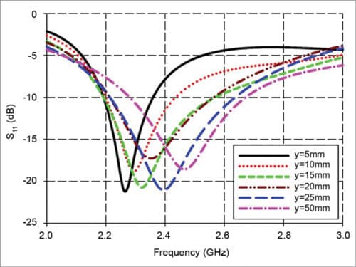
An antenna operating frequency is inversely proportional to inductance (L) or capacitance (C). These parameters are sensitive to PCB RF ground size and the product’s plastic casing. A large RF ground plane and plastic casing increase effective capacitance. Plastic has a higher dielectric constant than air, so proximity of plastic to the antenna results in a higher effective dielectric constant. This also increases the electrical length of antenna trace, reducing the resonant frequency of the antenna.

For a good PCB layout, the better the ground provided for a quarter-wave antenna, the better it correlates with theoretical behaviour. Return path of the RF signal is in the ground plane beneath RF trace. For good RF performance, return path should be uninterrupted and as wide as possible. If ground plane is interrupted, return currents find the next smallest path around the interruption. This forms a current loop, adding undesired inductance, affecting impedance match between the radio and antenna, consequently, attenuating RF signal significantly. If ground plane beneath the RF trace is narrow, it does not behave like a microstrip and may have more signal leakage.
To maximise radiation in the desired direction, orientation of the antenna should be in line with the final product’s orientation. It is important for an antenna to match the network, because a lot of parameters in the antenna’s proximity can vary its impedance. Also, it is important to verify the antenna matching network with the final plastic enclosure and the product placed in practical use.
Shriram Shinde, application engineer, CoreEL Technologies, says, “Parameters like frequency, power of operation, gain, voltage standing-wave ratio, front-to-back ratio, impedance, termination, beam width, efficiency of operation and polarisation status decide the geometry of an antenna for an RF application.”
Design criteria for space applications
During a design cycle, control of scattering is necessary so that the impact of spacecraft body and component on RF performance is negligible. High-power issues, such as multi-paction, passive intermodulation (PIM), electrostatic discharge (ESD) and so on, must also be considered during design.
In addition to RF design, structural design, thermal control and material qualification is also important for space applications. Feed return loss and port-to-port isolation should be optimised to maintain the above-desired specifications.
Dr Ramesh Chandra Gupta, scientist – antenna systems, Indian Space Research Organisation (ISRO), explains, “The key element of an antenna for space applications relies on its functionality and application. For high-power satellite communication, different types of reflector antennae are used. These are illuminated by the feed system.
“Design of an onboard antenna depends on many factors and constraints. Maximum diameter of the antenna is constrained by size of fairing of the launch vehicle. Configuration and optics of the antenna and shape of its surface to achieve specified edge of coverage (EoC) gain over coverage area. Optimising cross-polarisation discrimination (XPD) and suppressing power helps avoid interference.”
A good GPS antenna design should have a stable phase centre over a wide range of elevation angles to minimise antenna performance impact on position accuracy of the receiver connected to the antenna. Also, it is necessary to achieve a smooth gain change over the elevation plane to receive signals from satellites appearing very close to the horizon.
Sasa Dragas, radar antenna developer, RYMSA RF, says, “Antenna design is faced with many demands depending on application. A satellite receiver antenna should provide a very low noise together with low noise amplifiers. It requires careful matching of antenna output impedance to obtain optimum noise match. On the other hand, a transmitting satellite antenna should accomplish a strict radiation pattern mask, so it does not interfere with adjacent satellites.”
Selection of antenna feed
Antenna feed can be considered as a part of the antenna because it provides an efficient flow of EM energy, adequate antenna excitation as well as interface with the rest of the communication chain. These purposes determine the selection of the antenna feed.
In some cases, antenna feed is defined by special operational conditions. In case of high-power applications, such as radar or deep-space ground station, a feeding system needs to exhibit resistance on corona discharge effect, which could seriously damage the antenna. Therefore usually-used waveguide lines for feeding the antenna should be designed and tested according to this requirement.
Antenna feed selection is also based on the function of the antenna. Selection of a feed system is decided by bandwidth, edge taper subtended by reflector, cross-polarisation and accommodation.
Dragas adds, “A printed antenna array feeding system is distributed all over the antenna surface, bringing EM energy to each radiating element. This implies that strong coupling by radiation can appear between feeding lines and radiating elements, deteriorating overall antenna performance.
“This can be overcome by using a multi-layer technology where the feed is printed on a separate substrate layer. And through small-slot aperture on ground plane is coupled only with a specific point of the radiating element, which is printed on the other substrate layer.”
Dr Gupta comments, “An antenna for high-gain, multiple-spot beam for a high-throughput application, such as fast Internet, requires n number of displaced feed for n number of beams. So a high-efficiency, multi-mode, smooth-walled feed is desirable, due to its accommodation point of view. For a high data rate antenna, multiple high gain is essential.”
Selection of antenna for RF applications
Selection of the geometry of an antenna depends on its requirement to minimise scattering and blockage, thermal point of view, waveguide routing losses and so on. Sufficient offset of the main reflector is required to avoid blocking the feed and/or sub-reflector. Feed aperture is dependent on main reflector diameter, focal length and roll-off requirements, among others. Return loss and port-to-port isolation at feed port in presence of the reflector antenna is crucial.
Dr Gupta explains, “Selection of antenna for satellite communication depends on EoC gain, XPD, return loss, isolation, roll-off, beam steering, pointing error and other factors. It is an iterative and trade-off-based decision to select geometry of an antenna for satellite communication.”
Dragas adds, “Advances in numerical analysis and appearance of powerful computer-aided design tools make it possible to boost the design of completely new antenna types and accurately predict their performances.”
Conclusion
Usually, there is no unique solution for a particular RF application, hence, some guidelines are needed. For example, in case of an airplane, a very high parabolic reflector can cause high wind load and additional fuel consumption. So it is better to try a low-profile, flat-panel solution based on passive or active antenna arrays. This helps in the fulfillment of regulations regarding antenna radiation patterns imposed by satellite service operators.
Antenna radiating surface size is proportional to antenna gain, and its efficiency is usually related to its volume. In many cases, the best solution is a matter of making a compromise regarding operational requirements.
