

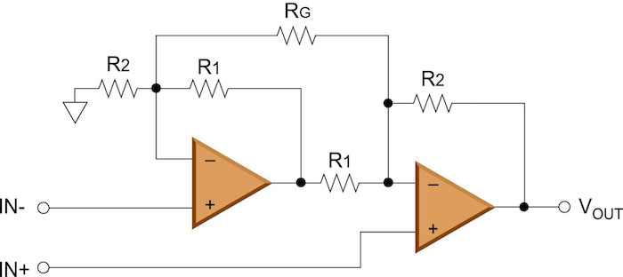
Figure 2 illustrates the popular instrumentation-amplifier circuit based on two amplifiers. In this circuit, the overall gain is set via one resistor, noted below as “RG”, such that:
![]()
One of the limitations of this circuit architecture is that it does not support unity gain. Although most instrumentation amplifiers are used to provide gain (and hence unity gain is not critical), some applications specifically use an instrumentation amplifier strictly for common-mode rejection. So, it is reasonable to assume that an INA may be used in a unity-gain configuration for some applications. Another limitation of the two op amp INA is that the common-mode range of the input is limited, especially at lower gains and when used with single-supply op amps. Keep in mind that the amplifier on the left-hand side of Figure 2 must amplify the input signal at the non-inverting node by 1+. So, if the common mode of the input signal is too high, the amplifier will saturate (run out of headroom on the output). At higher gains, there is more amplifier headroom and hence the circuit can support a wider input signal common-mode range, all else being equal.

One of the limitations of the difference-amplifier circuit discussed previously was the low input impedance. As can be seen in Figure 2, the two op amp INA circuit does not have this issue, since the two differential input signals feed directly into the input pins of the amplifiers, which generally have impedances in the millions of ohms. However, due to the difference in the input signal paths, there is a delay difference between the differential input signals, which results in poor common-mode rejection across frequency—a critical specification for instrumentation amplifiers. Similar to the difference-amplifier circuit, the common-mode rejection at DC is once again limited by the matching of the resistor ratios.
A monolithic INA that is based on this two op amp architecture will inherently have better resistor matching and temperature tracking, relative to a discrete solution, as silicon-based resistors can be trimmed to provide matching on the order of 0.01%. Still, the two op amp INA architecture has some definite limitations that cannot be overcome without changing the architecture of the circuit.
Three Op Amp INA
The second common INA circuit is based on three operational amplifiers, as shown in Figure 3. One may notice that the back half of this circuitry is identical to the difference amplifier that was previously discussed. The addition of two operational-amplifier buffers on the front end of the circuit provides a high, well-matched impedance source. This alleviates one of the main concerns with the simple differential circuit. The differential amplifier at the end provides the rejection of the common-mode component.


