


In industrial settings, including process and power plants, electrical personnel sometimes encounter unexplained issues such as the tripping of machines, process motors, HV/LV circuit breakers, and diesel generators. These issues can occur during both the starting and running phases of electrical equipment.
Even though field control panels are provided with alarm systems or data loggers in the main control room, they may not always reveal the exact cause of a fault. In such situations, this fault finder becomes a valuable tool for Fault Detection and Diagnostics in Equipment Maintenance
Presented here is a fault finder circuit based on the STM32 Blue Pill development board. Eight digital inputs and an analogue input are chosen for fault recording. The STM32 board, connected to a laptop computer with the provided Arduino program open and its serial monitor window active, will print the input number, contact status (logic 0 or 1), and its operation time in milliseconds whenever a change in contact state occurs. The ‘serial print’ feature of the Arduino IDE is used to record the status and operation time of the inputs.

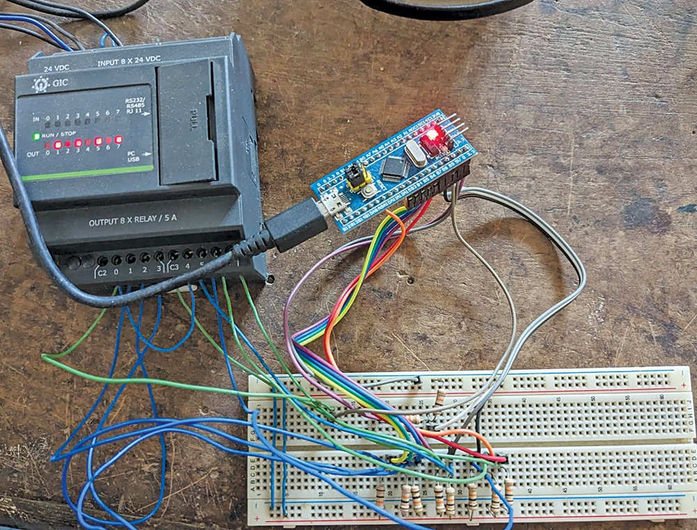
The purpose of this device can be explained with the help of the prototype shown in Fig. 1. If all contacts are closed/through, then the final relay-M will energise to start and run the motor/equipment continuously.
Demo Video
In case one or more contacts open, the relay-M will de-energise to trip the equipment. However, determining which contact initiated the trip can be challenging. In such situations, if the suspected and available duplicate logic contacts of the circuit are wired to this ‘fault finder,’ the first faulty contact can be identified from the contact changeover time recorded in the laptop’s Arduino IDE serial monitor. Thus, the fault can be easily found, analysed, and rectified in a brief time.

The prototype on a breadboard is shown in Fig. 1. The components required to build this device are given in the Bill of Materials table.
