
 Wheelchairs are useful for people for whom walking is difficult or impossible due to some illness, injury or disability. There are different types of wheelchairs. Manual wheelchairs are pushed using their handles. Motorised wheelchairs, are driven by joystick.
Voice-controlled wheelchairs are the latest development. These can be driven just by giving voice commands. A more advanced and intelligent version of the wheelchair is controlled directly through human mind, such as the one used by renowned scientist Stephen Hawking.
In case a person is unable to move the wheelchair even with joystick or voice command, an alternative is a gesture controlled wheelchair. The wheelchair moves as per user’s finger gestures. The user has to simply bend his fingers to move the wheelchair.
Here we present the project to control a wheelchair through finger gestures. It uses flex sensors to record finger gestures. The gesture signals are fed to ATmega32 microcontroller, which processes the information to control four DC motors in order to move the wheelchair in any desired direction.
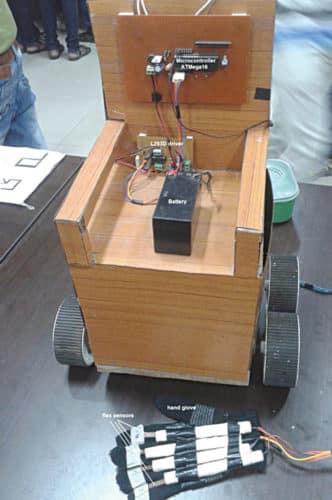
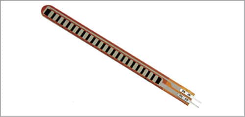
Flex sensors are widely used to convert finger gestures into equivalent electrical signals. These are actually variable resistors, whose resistance changes when these are bent in either direction. This change in resistance is converted into an equivalent voltage, which can be used for further processing. The author’s prototype including the sensor arrangement is shown in Fig. 1. Flex sensor used by the author is shown in Fig. 2.

System block diagram
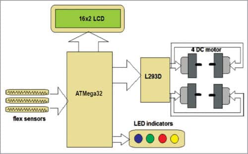
Block diagram for gesture control of a wheelchair is shown in Fig. 3. Major building blocks of the system are flex sensors, microcontroller ATmega32, motor driver L293D, DC motors, LCD display and LED indicators.
Flex sensor
It converts finger gestures into analogue voltages, which are fed to the microcontroller.
ATmega32 microcontroller
It performs the following tasks:

1. Takes flex sensor input from the internal analogue-to-digital controller (ADC) and checks whether it exceeds certain threshold limit when the sensor is bent
2. Rotates right and left motors in forward or reverse direction to move the wheelchair in the desired direction
3. Displays wheelchair movement on the LCD and also displays the direction of the wheelchair through LED indicators
LCD
It displays messages about the wheelchair’s movement direction as well as other messages
L293D driver
It provides sufficient voltage and current for DC motors to drive the wheelchair
DC motors
The four DC motors move the wheelchair in all the four directions: forward, reverse, left and right. Two motors (front and rear) on one side, say left side, are connected in parallel. Similarly, the other two motors on the right side of the wheelchair are connected in parallel. So there are four motors for four wheels, with one motor for each wheel.
LED indicators
These indicate the wheelchair’s direction of movement (forward, reverse, left or right).
Circuit and working
Circuit diagram of the gesture controlled wheelchair using ATmega32 is shown in Fig. 4. As mentioned earlier, it is built around four flex sensors (FS1 through FS4), an ATmega32 microcontroller (IC1), a 16×2 LCD (LCD1), an L293D motor driver (IC2), four 12V DC motors (M1 through M4) and a few other components.
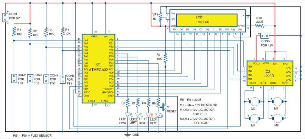
Flex sensors (FS1 through FS4) are configured in pull-up configuration with 10-kilo-ohm pull-up resistors. Flex sensor outputs are connected to ADC input pins 37 through 40 (PA3 to PA0) of IC1.
Port-D pins PD0 through PD7 of IC1 drive data pins D0 through D7 of LCD1. Control pins RS and EN of LCD1 are connected to port-C pins PC0 (pin 22) and PC1 (pin 23) of IC1, respectively. R/W pin is connected to ground to make LCD1 write always. A 1-kilo-ohm preset (VR1) is connected to VO pin of LCD1 to vary its contrast. Pin 15 of LCD1 is connected to +5V through 220-ohm resistor R10 and pin 16 to ground to turn on the back light of LCD1.
Port-B pins PB0 through PB3 (pins 1 through 4) of IC1 are connected to input pins of IC2. DC motors are connected to output pins of IC2.
Port-B pins PB4 through PB7 (pins 5 through 8) of IC1 drive the four LEDs through a 220-ohm current-limiting resistor each. AVCC (pin 30) and AREF (pin 32) of IC1 are given 5V to supply voltage and reference voltage for the internal ADC. A 10-kilo-ohm resistor (R5) is connected between Vcc and reset pin 9 (RST) of IC1. To make reset pin active-low, pushbutton switch S1 is connected between pin 9 and ground to apply active-low reset signal to IC1. Fuse bits are set such that IC1 works with the internal RC oscillator frequency of 1MHz. So you need not connect any external crystal at pins XTAL1 (pin 12) and XTAL2 (pin 13) of IC1.
Flex sensors, LCD1, ATmega32 and L293D all are given 5V, while L293D works off 12V supply.
Software
Complete working of the circuit is controlled by the software program (flex.c), which is already loaded into the internal flash memory of ATmega32 microcontroller. The program is written in ‘C’ language using AVR Studio software for the AVR microcontroller, and compiled and simulated using AVR simulator available with AVR Studio.
The program scans all the four ADC channels of IC1 and converts analogue input voltages from flex sensors FS1 through FS4 into digital equivalent hex values, and further into decimal values. The decimal value is around 700 when the flex sensor is straight and 850-900 when the flex sensor is completely bent. So the threshold limit is set to 820.
If none of the sensor values is more than 820, that means all the sensors are straight, i.e., the wheelchair is not moving. If any sensor value exceeds this threshold limit, the corresponding motor starts rotating. Simultaneously, a message is displayed on LCD1 along with indication on the corresponding LED.
While testing at EFY Lab, PROGISP programmer was used to program the IC.
Download Source Folder
Construction and testing
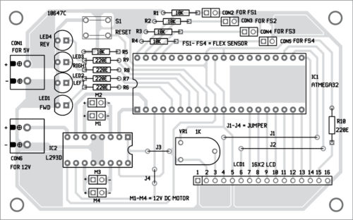
An actual-size PCB layout for ATmega32-based gesture control of a wheelchair is shown in Fig. 5 and its components layout in Fig. 6. After assembling the circuit on the PCB, enclose it in a suitable box.
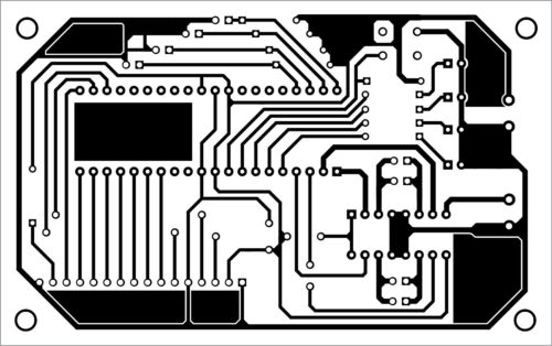
Download PCB and component layout PDFs: click here
Fix CON1 and CON2 on the back side of the cabinet for connecting 5V and 12V power supplies, respectively. Affix switch S1 (used for resetting the circuit) on the front side. Attach four sensors (FS1 through FS4) to your four fingers such that you can bend all the fingers easily along with sensors.
Operation. Initially, LCD1 displays the message “Gesture control wheel chair.” Then it displays the direction of motor movements. If the gesture controlled wheelchair is not moving, LCD1 displays the message “Wheel chair is stopped.”
When all the fingers are straight, it means all the sensors are straight. The output from a straight sensor is less than the threshold limit, so the microcontroller does not give signals to any of the motors. So the wheelchair does not move.
First finger
Now, if you bend your first finger (index finger) with FS1 sensor attached to it, the output from FS1 exceeds the threshold limit. The microcontroller reads its value and rotates all the four motors forward. So the wheelchair moves in forward direction. LCD1 displays the message “wheel chair is moving forward” and LED1 glows to indicate that the wheelchair is moving forward.
Second finger
When you bend your second finger (middle finger), the output from FS2 exceeds the threshold limit. The microcontroller reads its value and rotates both the right-side motors forward. So the gesture controlled wheelchair turns left. LCD1 displays the message “wheel chair is turning left” and LED2 glows to indicate that the wheelchair is turning left.
Third finger
Similarly, when you bend your third finger, the output from FS3 exceeds the threshold limit. This time the microcontroller rotates both the left motors forward. So the wheelchair turns right. LCD1 displays the message “wheel chair is turning right” and LED3 glows to indicate that the wheelchair is turning right.
Fourth finger. Finally, when you bend your fourth finger, the output from FS4 exceeds the threshold limit. The microcontroller rotates all the four motors in reverse direction. LCD1 displays the message “wheel chair is moving reverse” and LED4 glows to indicate that the wheelchair is moving in reverse direction.

is their any need for programming the ic before connecting a ckt.