
 This graphic equaliser uses low-cost op-amps. Good quality op-amps powered by a single voltage supply are readily available in the market. The op-amp should have a noise density of less than 24nV/ VHz, slew rate of more than 5V/µs and gain-bandwidth product greater than 3 MHz. The NE5532 or LM833 used in this circuit meets these requirements.
What’s an equaliser?
Equaliser circuits typically divide the audio spectrum into separate frequency bands and have independent gain control for each band. The output of each band is mixed at IC4(A) and then fed to an audio power amplifier. Proper quality factor (Q) needs to be selected to avoid overlap in adjacent bands as this introduces colouration into the audio signal.
We have used the multiple-feedback bandpass filter topology shown in left-most corner at the bottom of the figure. This is a circuit for single-channel bandpass filter. If the capacitors are of the same value, the calculations are fairly simple. For calculating the component values, use the following formulae:
Centre frequency (fo) : 2 C V
Bandwidth (B) : 1/CRc
Quality factor (Q) : fo/B = foCRc
Gain (A) : –Rc/2Ra
These can be combined to give the following formulae:

Ra = Q/2foAC
Rb = Q/2foC (2Q2–A)
Rc = Q/foC
Begin the calculations by choosing a large value of capacitance (~0.1F) and smaller value of resistances. Increasing the capacitance decreases resistances (Ra, Rb and Rc). Care must be taken to avoid overloading on the input buffer op-amp. Note that stray capacitances on the board reduces the value of ‘C.’ The bandwidth and gain do not depend on Rb. Hence, Rb can be used to modify the mid-frequency without affecting the bandwidth and gain.
For equalisers, there are standard mid-frequencies that are normally used. The exact frequencies depend on the octave division, application and some degree of manufacturers’ preference, but nearly all share the basic octave boundaries that are based on a centre frequency of 1000 Hz.
A balance between the number of filters and bandwidth need to be observed. It is possible to use a wider bandwidth and fewer filters, or narrower bandwidth and more filters. Anything narrower than 1/3 octave is rare, since the complexity of the filters increases for higher values of ‘Q.’ This can get rather expensive and in reality is of limited use for most applications in audio systems.

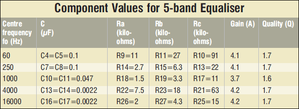
National Semiconductor lists the following mid-frequencies for a 10-band graphic equaliser: 32, 64, 125, 250, 500, 1k, 2k, 4k, 8k and 16k. It also recommends a ‘Q’ of 1.7 for equalisers.
The table lists the component values for different centre frequencies of the equaliser. We used ‘Q’ of 1.7 and gain (A) of 4.
Graphic equaliser circuit
The circuit for the 5-band graphic equaliser uses IC1 (A) LM833 as the buffer stage for the equaliser. It is a non-inverting amplifier with a gain of ‘2.’ The input signal is divided by ‘2’ by the resistive network comprising R3 and R4. Hence the net gain of this amplifier is unity. Two 100k resistors (R1 and R2) are used as a voltage divider and the junction voltage is fed to its positive input through R6. This divider has enough power to feed all other op-amps directly. Resistor Ro (R8=R12=R16=R20=R24=R28=R30=100W) has the dual function of noise reduction and resistive isolation of capacitive load. It may be varied between 50 and 150 ohms depending on the noise in the circuit.
The potmeters (VR1 through VR5) are in the signal path and hence should be of the best quality possible. Wrap the body of the pots with bare copper wire and solder the other end of the wire to ground. Since the filters are very sensitive, all resistances should be metal-film type and the capacitors should be polyester type.
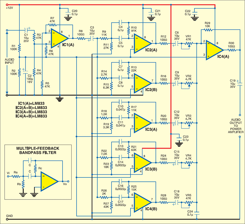
Each stage of the op-amp needs to be capacitively coupled to the next stage so that the DC does not get propagated and amplified. For a good low-frequency response, this coupling capacitor should be greater than 1 µF. A 10µF, 16V capacitor is used in each stage of the circuit here.
The circuit is powered by a 12V DC regulated supply. A well-regulated supply using 7812 is recommended. Ground the Vcc pin of each op-amp with a 0.1µF ceramic disk capacitor to bypass the noise.
The article was first published in May 2007 and has been recently updated.


what is V in the formula Centre frequency (fo) : 2 C V
How one can calculate centre frequency using these formula.
do you have a CB layout for your 5 band equalizer