 Assemble yourself a portable, four-channel multi-mode light controller using an Arduino Uno board and very few external components.
The fancy lights controller described here is built around the Arduino (an Open Source single-board microcontroller) platform that can be purchased in pre-assembled hardware form. The circuit is nothing but a portable four-channel, multi-mode digital light controller, realised using very few external components. Four LEDs are made to glow in different sequences and patterns, controlled from the Arduino board (Fig. 1).
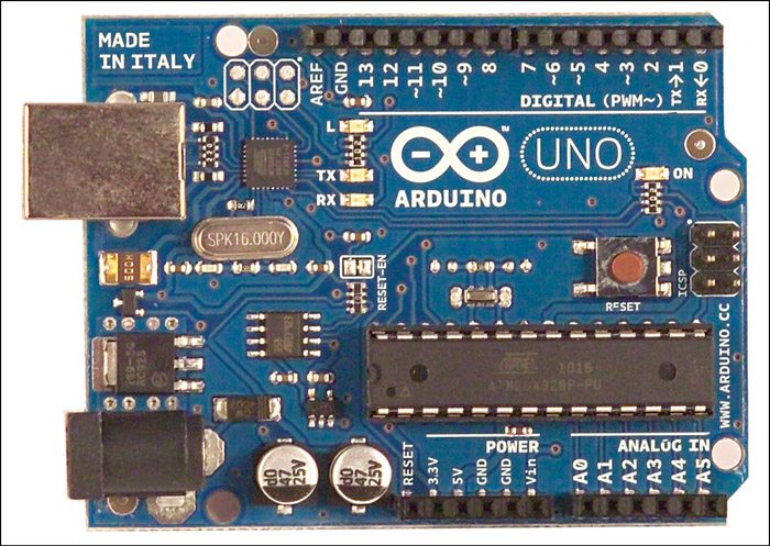
For this project, in addition to an Arduino UNO board, you need a USB cable (A to B), PC running the Arduino IDE (0022), components (four LEDs and 220-ohm resistors, a 10-kilo-ohm resistor and a switch), accessories (wires, connectors and battery), and the code or sketch for the MCU.
In the prototype, four 5mm red LEDs (LED1 through LED4) are used at the output. However, the same output lines can also be used to control high-voltage incandescent lamp strings with the help of suitable solidstate light switch modules. A push-to-on microswitch (S1) is the one and only output mode selector in the circuit!
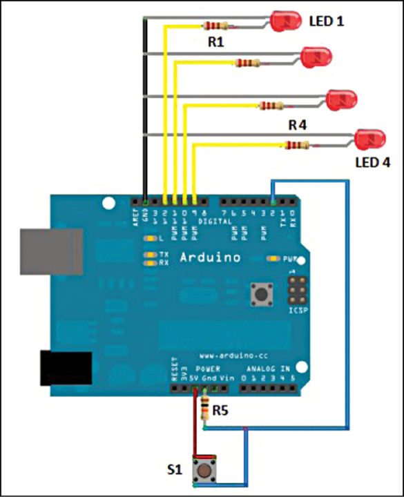
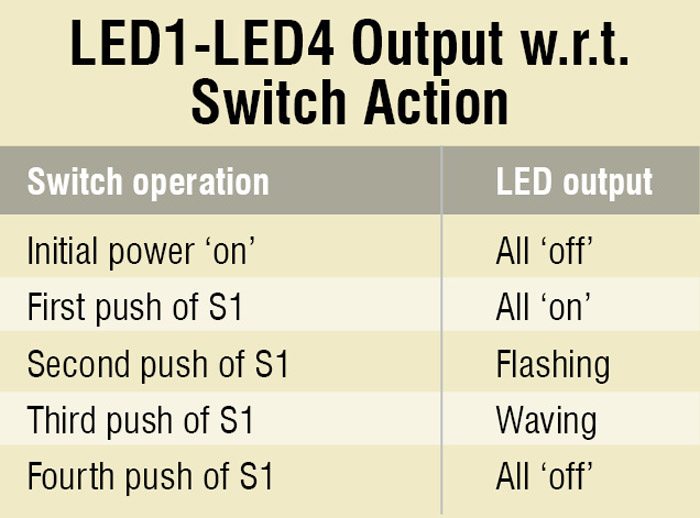
The screenshot of fancy lights controller wiring generated using Open Source Fritzing software is shown in Fig. 2. The table shows the function of switch S1 and corresponding output on LEDs (LED1 through LED4).
Arduino
The Arduino board is an easy-to-use yet powerful single-board computer that has gained considerable traction in the hobby and professional market. It is Open Source, which means the hardware is reasonably priced and the development software free. An important feature of the Arduino is that you can create a control program on the host PC, upload it to the Arduino board and it will run automatically. This means that you connect the board to the host PC to develop and debug your program, but once that is done you no longer need the PC to run the program.
 Uno is one of the series of USB Arduino boards. The Arduino Uno is a microcontroller board based on the ATmega328. It has 14 digital input/output pins (of which six can be used as PWM outputs), six analogue inputs, a 16MHz crystal oscillator, a USB connection, a power jack, an ICSP (in-circuit serial programming) header and a reset button. It contains everything needed to support the microcontroller; simply connect it to a computer through a USB cable or power it with a 9V DC adaptor (or 9V battery) to get started.
Getting started with Arduino (Windows)
Get the latest version of Arduino environment in zip format from the download page. When the download completes, unzip the downloaded file.
Double-click the folder to open it. There should be a few files and sub-folders inside. Make sure to maintain the automatic folder structure after download. Connect the Arduino board to your computer using the USB cable. The green power LED (labelled PWR) on the Arduino Uno board should glow.

Wait for Windows to begin its driver installation process. After a few moments, the process will fail. Don’t worry! Just click ‘Start’ menu, and open up ‘Control Panel’. While in the control panel under ‘Category View’ option, navigate to ‘System and Security.’ Next, click ‘System.’ Once ‘System’ window is up, open ‘Device Manager.’ Look under ‘Ports’ (COM and LPT). You should see an open port named ‘Arduino UNO (COMxx).’ Right-click ‘Arduino UNO (COMxx)’ port and choose ‘Update Driver Software’ option. Next, choose ‘Browse my computer for driver software’ option. Finally, navigate to and select the Uno’s driver file ‘ArduinoUNO.inf,’ located in ‘Drivers’ folder of the Arduino software download. This completes the driver installation process of Windows.
Wire the electronic circuit
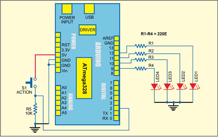
Follow the wiring diagram shown in Fig. 4 to assemble the lights controller circuit. After construction and physical inspection of the circuit, plug the USB cable of the Arduino into your computer, compile the sketch (Fancy_Lights.pde) and upload it to the Arduino.
Uploading the sketch to Arduino
To upload the sketch, go to your newly unzipped Arduino folder and look for the Arduino IDE icon. Double-click the icon to open the IDE. You will be presented with a blue and white window. Note that before uploading the sketch, you need to tell the IDE which Arduino board and USB port you are using. Go to ‘File’ menu and click ‘Tools,’ then click ‘Board’ option. You will be presented with a list of different Arduino boards that can be connected to the IDE. Choose ‘Arduino UNO.’ Next, select your USB port. Click ‘Tools’ again and scroll down to ‘Serial Port.’ A list of the available serial ports on your system will be displayed. Choose the one that refers to your USB cable.
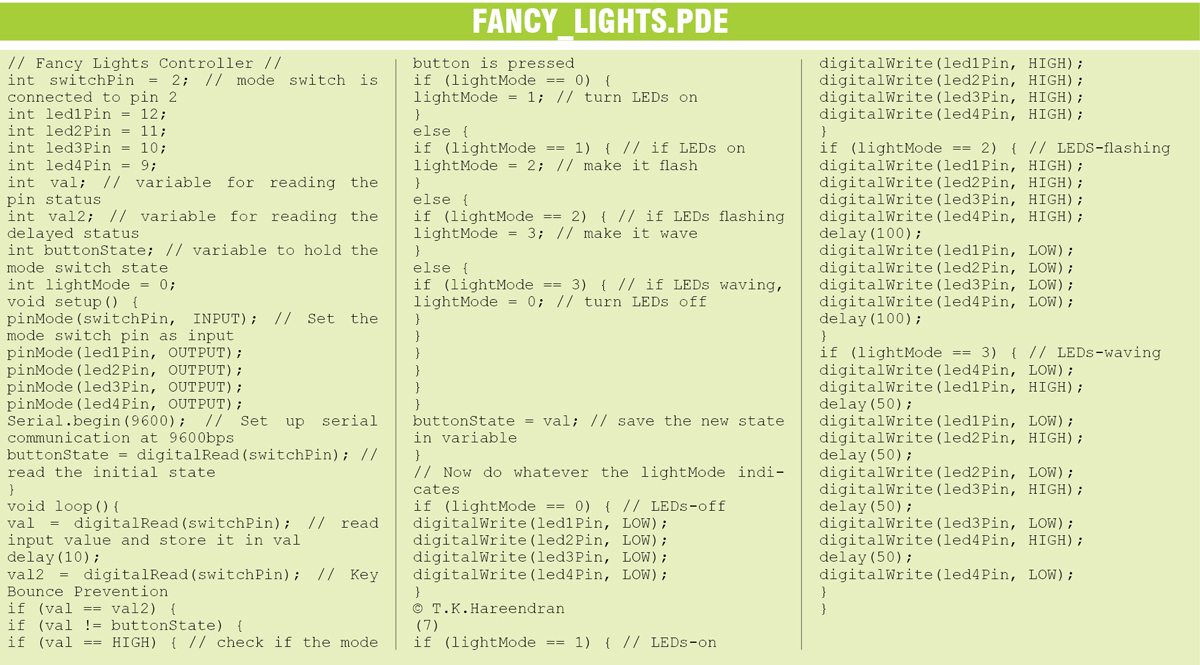
Now, click ‘File’ in ‘File’ menu and select ‘New.’ Here you can type or copy and paste the code inside the code window. Click ‘Verify/Compile’ button to check that the code is correct. If everything is fine, upload the code to your Arduino by clicking ‘Upload’ button. Presuming everything has been set up correctly, you will now see the RX and TX LEDs on the UNO board flash (switch on and switch off) very quickly while data is being uploaded to the MCU in the board. After the data is uploaded to the board successfully, you will get a “Done Uploading” message in the IDE and the RX/TX LEDs will stop flashing. The Arduino will now reset itself and immediately start running the sketch that you have just uploaded.
If everything is okay, remove Arduino from the computer and use it as a standalone unit. You can run the board from a 9V alkaline battery or a 7V-12 DC power supply using a standard 2.1mm male DC Jack plug.
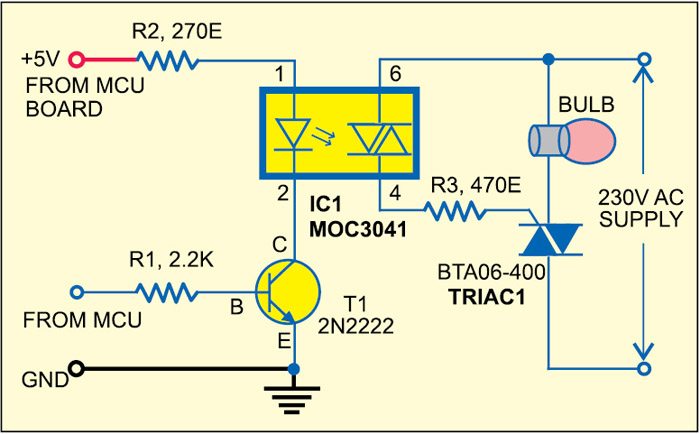
This circuit can also be used to drive 230V AC mains input lamps instead of LEDs. For this, you need to assemble four solidstate light switch modules with galvanic isolation (and zero-crossing) as shown in Fig. 5.
Download source code: click here
The author is a freelance writer and regular contributor to EFY


How does the curcuit work?
All the information is provided in the article itself.
Can you send the source code for this?
No source code .. Pretty useless.
Hi David, the source code is present at the end of the article.
Hii
great thanks for sharing awesome info . I really love your led project so will implement your way . keep it up with such cool project thanx once again
Thank You for your feedback.