
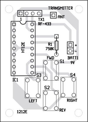
HT12E is permanently enabled for transmission by connecting its TE pin to ground. When any switch, say, S1, is pressed, the corresponding data is serially transmitted from DOUT pin through the RF ASK transmitter module. A 9V battery is used to power the circuit.
Download PCB and component layout PDFs: click here
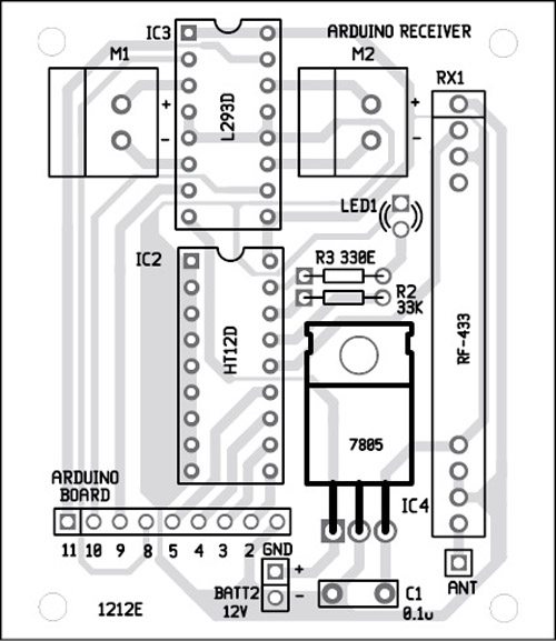
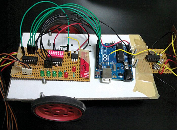
Receiver and motor driver circuit. Assuming that address pins on the encoder and the decoder are identical, when any of the switches on the transmitter (marked as FWD, REV, RIGHT, LEFT) is pressed, the corresponding data pin of the decoder goes low. The data outputs from D8 through D11 of HT12D (IC2) are fed to pins 2 through 5 of Arduino UNO board to generate appropriate logic outputs from pins 8 through 11 of Arduino UNO board.
Outputs from pins 8 through 11 of Arduino Uno board are fed to IN1 through IN4 of L293D (IC3) to drive both the motors M1 and M2 as shown in Fig. 3. Outputs OUT1 and OUT2 drive motor M1, and outputs OUT3 and OUT4 drive motor M2. Enable pins EN1 (pin 1) and EN2 (pin 9) are connected to Vcc for always enabled output. Regulator 7805 (IC4) provides regulated 5V to the receiver.
Construction
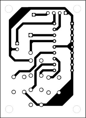
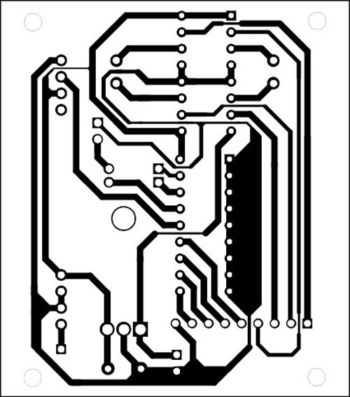
A single side PCB for the RF transmitter (Fig. 2) is shown in Fig. 4 and its component layout in Fig. 5. The PCB for the receiver (Fig. 3) is shown in Fig. 6 and its component layout in Fig. 7. A suitable connector arrangement has been made on the RF receiver PCB in order to extend connections to the drive motors and the battery mounted on the chassis of the RF robot.

Download source code: click here
Software
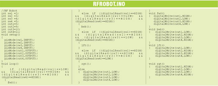
The source code file (RFROBOT.INO) for this project is listed at the end of this article. The Arduino Uno is programmed with Arduino IDE software. The ATmega328 on Arduino Uno comes pre-burned with a bootloader that allows you to upload new code to it without using an external hardware programmer. It communicates using the original STK500 protocol. You can also bypass the bootloader and program the microcontroller through the ICSP (in-circuit serial programming) header but using the bootloader makes the programming quick and easy.

Select Arduino Uno from the Tools→Board menu (according to the microcontroller on your board) in the Arduino IDE and burn the program through the standard USB port in the computer.
The author is a B.Tech in electronics and communication from Lovely Professional University

In PDF file transmitter or remote print layout of is not there please upload the remote PCB layout print
Dear
Pls , where I can find the PCB best regard
It is present on the second page.
what do you call the red board with ON written on it and having switche along the 1,2,3… along IC?
Are the inputs “latched” or can it be made to do so? I’m looking for a way to press the button (fwd), and have it keep moving without having to hold it. Then switch off when the opposite button (rev) is pressed, or add in a stop button.
If that was silly, forgive me, I’m very new to this.
Contact me for pcb design.. of any type and pcb…NAUTEC Bhopal M.P
why cannot work
Kindly elaborate your query.
I made a smartphone controlled robot
https://www.youtube.com/watch?v=jbXdEmjqVcA
sir iam unable to open pcb layout of transmitter pls fix this issue.
sir please send me transmitter pcb layout to this email id..
This is okay but how connect servo motor with this type of circuit
Can we replace l293d with l298
Motor is not running though i have checked the connection 5-10/times and we also checked program.
There is no transmitterr circuit in pdf
as per diagram transmitter supply 9v how possible