
3D printing, getting popular for making usable objects, is the reverse of traditional machining where material is removed from a block by drilling, cutting, chiseling, etc for making objects. In 3D printing, an object is created by laying successive layers of material as per requirement. This article describes how you can assemble a simple 3D printer for yourself, like we did in EFY lab, and then make use of it. But before that, you should know some basics of 3D printing.
The process of printing 3D objects starts with making a virtual design of the object you want to create, using one of the supported computer aided design (CAD) software. A 3D scanner can also be used to copy an existing object. The scanner makes a 3D digital copy of an object and puts it into a 3D modeling program. This 3D model file is sliced into thousands of horizontal layers which are then printed by a 3D printer, layer by layer, creating the entire 3D object. 3D printers generally employ one of below-mentioned methods.
Fused deposition modeling (FDM)
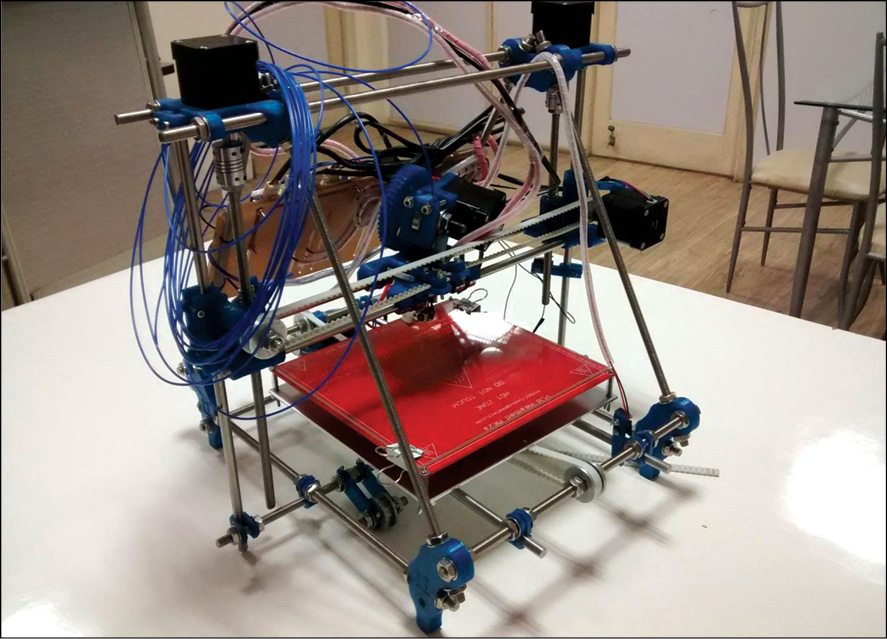
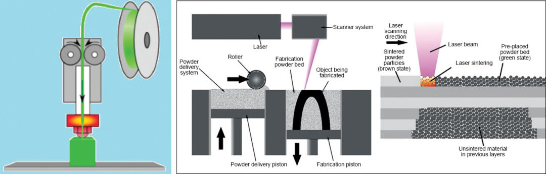
This is the most popular method used in DIY type 3D printers. Here a plastic filament or wire is made to pass through an extrusion nozzle (Fig. 2). The nozzle tip is heated to melt the filament or wire. The nozzle can be moved in all three directions, precisely, using stepper motors. The object is produced by extruding melted material to form layers upon layers of the object. The material hardens immediately after extrusion from the nozzle. The process is also known as fused filament fabrication (FFF). The printer shown in Fig. 1 is an assembled FDM based 3D printer.
Selective laser sintering (SLS)
In this method high-power laser is used to fuse small particles of plastic, metal, ceramic or glass powder to form an object. The laser selectively scans and fuses the material layer by layer as per the 3D model design. Once a layer is completely printed, the bed is lowered by one layer thickness and new layer of fused material is applied. The process is repeated until all the fused layers have been laid. Fig. 3 shows an SLS system.
Sterolithography (SLA)
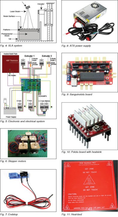
This method employs ultraviolet curable photopolymer resin and an ultraviolet laser to build the object’s layers. The laser beam scans a selective surface area of the resin to solidify it as per the 3D design model. Once a layer is printed, the platform descends by a distance equal to the thickness of a single layer. And the laser scans again to print the second layer. Fig. 4 shows and SLA system.

How to build a DIY 3D printer
The printer described here is the LM8UU Prusa Mendel 3D printer. The basics of building any FDM based DIY printer will be more or less the same. The printer has three major parts: electronics (and electrical), software and mechanics.
Fig. 5 shows the complete electronic and electrical system that runs a 3D printer. Sanguinolulu board is the heart of the whole system. It controls different stepper motors for moving the nozzle in X and Y directions, moving the heat bed in Z direction and extruding the material from the nozzle.
Fig. 6 shows the stepper motors used. The board senses extruder’s and bed’s temperature through thermistors. Endstops are used (like stoppers) by the printer to determine the boundaries. Fig. 7 shows an endstop.

The temperatures of nozzle and heat-bed can be monitored through software as explained in software section. The software program, which connects to the board through USB interface, is used for loading the 3D model file for printing and testing various operations. The overall system is powered by 12V, 400W ATX power supply (Fig. 8).
Sanguinololu board
Sanguinololu board (shown in Fig. 9) is a low-cost, all-in-one electronics solution for Reprap and other CNC devices. It features an onboard Sanguino clone using the ATMEGA644P microcontroller, though an ATMEGA1284 can be easily substituted. The board is developer-friendly with expansion pins supporting I2C, SPI, UART and ADC functions. Sanguinololu has a very flexible input power supply that ranges from 7V to 30V.
Pololu board
The stepper motors are powered by Pololu boards that are mounted over Sanguinololu board. These are carrier boards or breakout boards for Allegro’s A4988 DMOS microstepping driver with translator and over-current protection. The stepper motor driver lets you control a bipolar stepper motor at up to 2A output current per coil. Fig. 10 shows a Pololu board with heatsink.
Heat-bed
The heat-bed (Fig. 11) normally heats up to 110°C when powered through the dedicated connection on Sanguinolou board. The power supply should be able to deliver at least 300W and wires from the power supply to the Sanguinololu board should be capable of handling 20A or slightly more current.
Thermistor
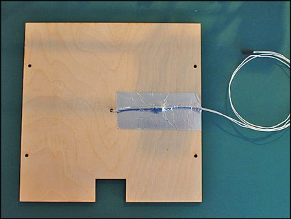
A thermistor is attached to the heat-bed using aluminium tape. The thermistor should poke through the central hole in the bed, about 1mm. Tape the thermistor securely and run the cable to the right (Fig. 12). The cable is connected to Sanguinololu board for monitoring the temperature of the heat-bed.
Extruder
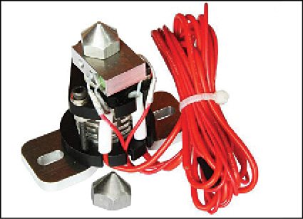
The extruder’s nozzle end heats up when enabled by the Sanguinololu board. The extruder assembly has an in-built thermistor to monitor and control the temperature of the hot end. A stepper motor rotates to push the raw material in the nozzle from the cold end; the speed can be controlled. The material melts when pushed through the nozzle’s hot end and gets placed on the heat-bed as per 3D model design. Fig. 13 shows the nozzle (extruder) assembly.
Software
All the software required for a DIY type 3D printer is available at:
http://www.nextdayreprap.co.uk/reprap-downloads/
The Sanguinololu board comes with boot-loader preinstalled. You just have to upload the 3D printer firmware. For that, first install Arduino development environment on your computer and add the Sanguinololu board in it. Download Sanguino software from: //code.google.com/p/sanguino/downloads/list
Copy the downloaded software in the Arduino installation directory under Hardware folder. The Sanguino boards will start reflecting in the boards menu of Arduino IDE. Now, select the board in the Arduino IDE corresponding to the microcontroller on the Sanguinolulu board. Download the 3D printer firmware (Marlin or Sprinter), open it in the IDE and click on Verify/Compile button. Click on Upload button to upload the firmware in the Sanguinololu board. Note that you might have to make some changes in the Configuration.h file as per your printer.
Once the firmware is uploaded, you just need software that can slice the 3D model design (.STL file) to make the .gcode file. This .gcode file is then given to the 3D printer for printing the object, layer by layer. The software that you can use here is Pronterface. Follow the steps below to install Pronterface and dependencies.
1. Install Python Environment & Dependencies. Download and install the ‘python-2.7.2.msi’ from http:// python.org/ftp/python/2.7.2/python-2.7.2.msi
2. Download and install PYSerial for serial communication from http://pypi.python.org/packages/any/p/pyserial/pyserial-2.5.win32.exe
3. Download and install Python 8 for Python from http://downloads.sourceforge.net/wxpython/wxPython2.8-win32-unicode-2.8.12.0-py27.exe
4. Download and install PYReadline also for serial communication from http://launchpad.net/pyreadline/1.7/1.7/+download/pyreadline-1.7.win32.exe
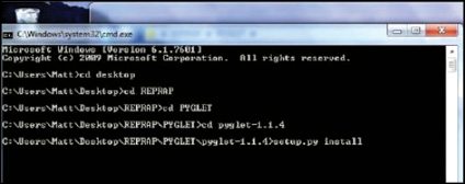
5. Now, install Pyglet. Download it from the link http://pyglet.googlecode.com/files/pyglet-1.1.4.zip
6. Extract the files. Run command prompt and navigate to the extracted directory. Type ‘setup.py install’ and press enter as shown in Fig. 14.
7. Download and install Pronterface from www.nextdayreprap.co.uk/downloads/kliment-Printrun-d9a3363.zip
Mechanical assembly
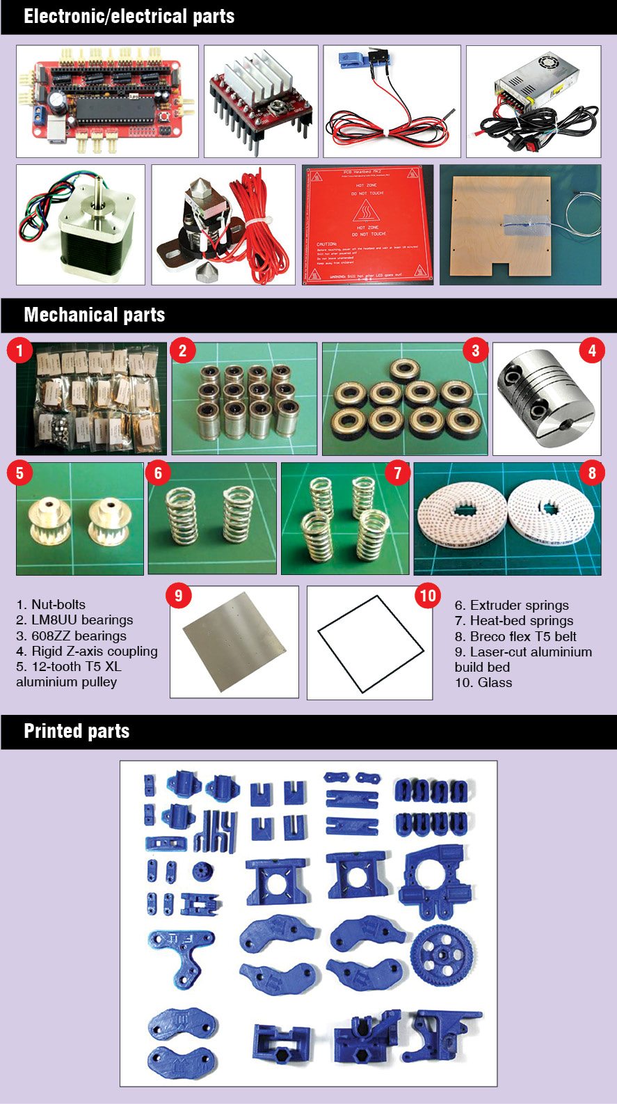
Mechanical assembly is the most critical thing in DIY type 3D printers as all the parts need to work precisely to print an object properly. Mechanical assembly instructions and architecture will differ from model to model. You may take help of Google to search for the kit or parts required to assemble your printer and further instructions, if required. The LM8UU Prusa Mendel 3D printer assembled at EFY required parts that are shown in the box on previous page.
Print a part
If you have done the mechanical assembly and software upload, the major task is over. Now you just have to use Pronterface software to print any 3D object. Start by connecting your 3D printer via USB cable to a computer that has Pronterface software installed already. Connect the ATX power supply to the 3D printer and switch it on.
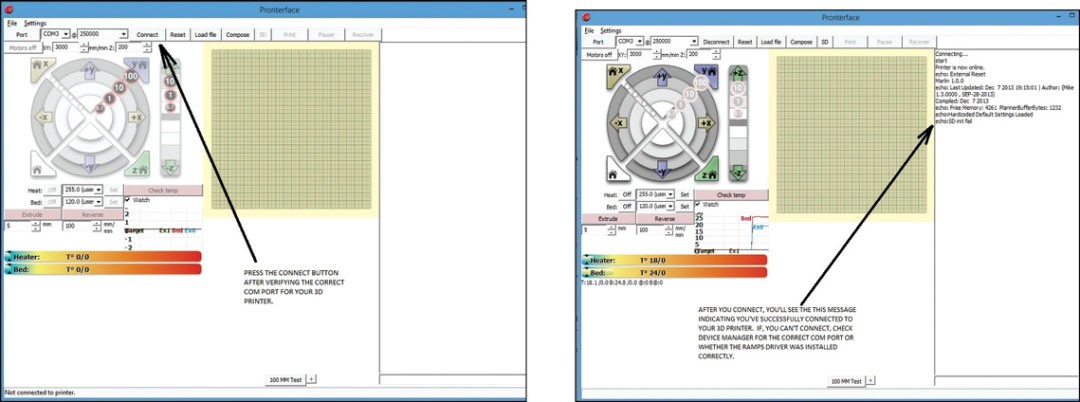
Run Pronterface software. Once the software is up, computer screen will look like as shown in Fig. 15. Select the COM port to which your 3D printer is connected and set the baud rate to 250,000 (as shown in Fig. 15). Next, click on Connect button. You will see message in the right column of Pronterface indicating that the printer has successfully connected as shown in Fig. 16.
Once connected, you can use Pronterface to manually control the X, Y and Z axis movements as shown in Fig. 17. You can also manually control the extruder motor using Pronterface, but be sure that the heater is turned on before doing so. The distance and speed of the manual control is set right below the Extrude button.
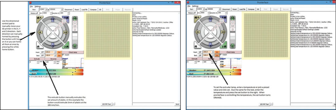
To set the temperature of the nozzle or heat-bed, use the pull-down menu and select the temperature and then use Set button as shown in Fig. 18. To turn the heating off, simply select the Off button. You can monitor the temperature of the nozzle and bed by selecting ‘Watch’ option and then viewing the graph of real-time temperature value. Or, you can select ‘check temp’ to view the actual temperature in the console on the right side.
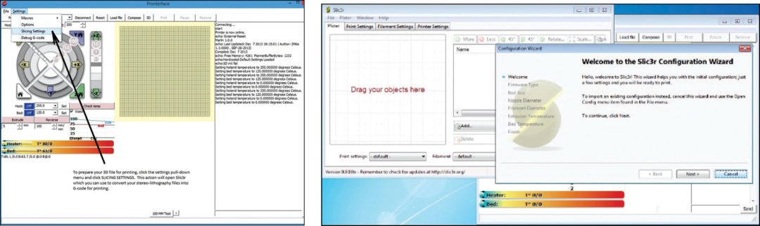
From the pull-down menu in the toolbar select Settings and then Slicing Settings as shown in Fig. 19. This will open the program Slic3r as shown in Fig. 20. Slic3r is the program to convert a digital 3D model into printing instructions for your 3D printer.
If this is the first time you are opening Slic3r, you will be prompted with the Slic3r configuration wizard. Select Cancel on this wizard.
Drag your .stl file of the object you want to print in the box as shown in Fig. 21. Click on the export G-code button and your G-code will be ready to load. Your 3D printer uses G-code to know what to print. The slicing program will convert a stereolithography (.stl) file of a 3D model into the necessary G-code that your printer can understand. Once the file has been exported into the needed G-code format, you can open that file in Pronterface for printing.
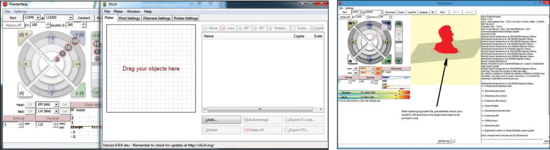
Open the G-code by navigating to the File menu and then clicking Open. Browse the folder you exported the G-code file into and select that file and then press OK. When Pronterface loads the file it will appear on the graph in the graphical user interface as shown in Fig. 22. Now you just have to click on Print on the Pronterface toolbar and your printer will start printing the 3D object, layer by layer.
Happy printing!
The author was a technical editor at EFY when he wrote this article. He has moved on since then to work on his own.


