
 This thermistor based fire alarm project can effectively be used as a temperature-sensing fire alarm. Here, an NTC thermistor is used as the temperature sensor. Resistance of the NTC thermistor decreases with an increase in temperature.
Thermistor based fire alarm circuit
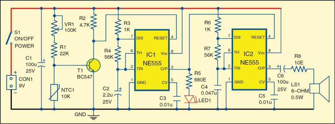
 Circuit diagram of the fire alarm is shown in Fig. 1. It is built around NTC thermistor (NTC1), transistor BC547 (T1), popular NE555 timers (IC1 and IC2), speaker and a few other components.
In this circuit, the two NE555 timers are wired as astable multi-vibrators. IC1 is wired as a low-frequency generator and IC2 as a high-frequency generator.
At room temperature, transistor T1 conducts and keeps reset pin 4 of IC1 at ground level. As a result, both timer ICs are disabled. But when temperature of the sensor goes above 70°C (depending on the thermistor constant [K]), transistor T1 stops conducting. Both NE555 timers oscillate and a beeping sound is heard from the speaker.
Potmeter VR1 is used to set the cut-off/saturation condition of transistor T1, which is related to the resistance of NTC1 at different temperatures. At room temperature, voltage at pin 4 of IC1 remains low. With heating of NTC1, voltage at pin 4 of IC1 becomes high. This enables both the timer ICs to oscillate and produce sound through the speaker. Also, LED1 starts flashing.

The circuit works on 9V regulated power supply. For a louder sound, you may add a speaker driver circuit with matched impedance.
Download PCB and component layout PDFs: click here
Construction and testing
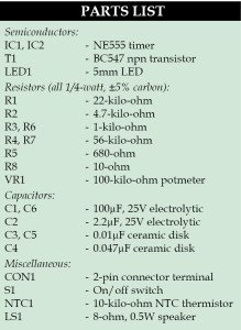
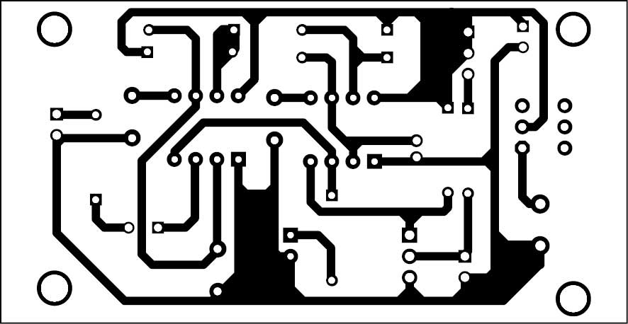
A single-side PCB for the fire alarm circuit is shown in Fig. 2 and its component layout in Fig. 3. Enclose the PCB in a small box in such a way that the thermistor can sense the temperature in case of fire.

Pradeep G. is B.Sc. (Physics) and a regular contributor to international magazines. He is also a small-business owner making school/college projects in south India

Can you explain the working principles of a more specific circuit. Thanks
what should i change if want to put a buzzer instead of the speaker
How can I contact you.
You can contact us at [email protected]